
Audio sync circuit

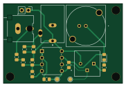
About the Audio sync circuit PCB
Audio sync circuit is an open source PCB design by melizalab, published on GitHub. It is a 2-layer board measuring 45.5 × 30.5 mm, with 13 components from 9 distinct parts.
Other key parts include the MCP6002-I/P. By type, the board carries 6 resistors, 3 capacitors, 1 IC and 1 diode.
It belongs with the audio designs in this gallery.
From the project
KiCAD files for a simple circuit that converts a synchronization pulse on an audio channel to a TTL pulse
This repository contains KiCAD files for a simple bistable multivibrator circuit to convert line-level pulses on an audio channel to TTL signals. The audio sync pulse is assumed to be the output from a sound card or DAC preamp, which means that it's line-level and probably has some high-pass filtering applied. For example, the open-ephys-audio script plays a short click on a separate channel so neural recordings can be precisely synchronized with the stimulus. These clicks work fine for an analog recording, but other hardware (e.g., inscopix miniscopes, optogenetic LED drivers) often requires…
Main components on the Audio sync circuit
Audio sync circuit bill of materials (BOM)
13 components, 9 distinct parts — part numbers from the project's BOM.
| Qty | Part | Footprint | Refs |
|---|---|---|---|
| 1 | MCP6002-I/P MCP6002-xP Microchip Technology | PDIP8_300MC_MCH | U1 |
| 1 | PJ-102AH | CUI_PJ-102AH | 5V |
| 1 | 3386P-1-104LF 100k Bourns Inc. | POT_3386P | RV1 |
| 1 | HSMY-C150 | LED_0805_2012Metric_Pad1.15x1.40mm_HandSolder | D1 |
| 2 | 1u | C_0805_2012Metric_Pad1.18x1.45mm_HandSolder | C1, C2 |
| 1 | 0.1u | C_0805_2012Metric_Pad1.18x1.45mm_HandSolder | C3 |
| 2 | 5k | R_0805_2012Metric_Pad1.20x1.40mm_HandSolder | R1, R5 |
| 3 | 10k | R_0805_2012Metric_Pad1.20x1.40mm_HandSolder | R2, R6, R7 |
| 1 | 200 | R_0805_2012Metric_Pad1.20x1.40mm_HandSolder | R3 |
Audio sync circuit design files
The KiCad project lives in the melizalab/audio-sync-circuit repository on GitHub; these links point at the commit this page was built from.
- Layoutaudio-sync.kicad_pcb
- Schematicaudio-sync.kicad_sch
- BOMBOM-oesync-v2.xlsx
Audio sync circuit: common questions
How big is the Audio sync circuit PCB?
The Audio sync circuit measures 45.5 × 30.5 mm, has 2 copper layers and is 1.6 mm thick.
How many components are on the Audio sync circuit?
13 components, from 9 distinct parts, with part numbers taken from the project's own BOM. The full bill of materials is listed on this page.
Where can I download the Audio sync circuit design files?
From the melizalab/audio-sync-circuit repository on GitHub, which has the KiCad layout, the schematic and the BOM; the links under Design files point to each one.
Can I use the Audio sync circuit design in my own project?
The repository has no license, so all rights stay with melizalab. Use it as a reference, and ask the author before reusing the design.
Similar boards
KLOR
GEIGEIGEIST
160.2 × 118.3 mm79 parts2LGPL-3.01.2k
ButtonsLEDs
shanteacontrols
390 × 37 mm82 parts2LApache-2.0956
USB
52 × 12.6 mm6 parts2LApache-2.0956
Pots
390 × 93 mm75 parts2LApache-2.0956
PicoGUS Hand386
polpo
29.2 × 75.2 mm43 parts4LGPL-2.0800
Snark barker
schlae
231.1 × 106.7 mm193 parts2LNo license687