
IMU-Stick

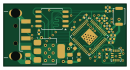
About the IMU-Stick PCB
IMU-Stick is an open source RP2040/RP2350 PCB design by Merlin2LmmL, published on GitHub under the Apache-2.0 license. It is a 4-layer board measuring 32.5 × 16.5 mm, with 27 components from 13 distinct parts.
Its main chip is the RP2040, from the RP2040/RP2350 family. Other key parts include the ICM-42688P-HXY, W25Q128JVS and NCP1117-3.3_SOT223. By type, the board carries 17 capacitors, 4 ICs, 4 resistors, 1 connector and 1 switch.
It belongs with the sensors and robotics & motion designs in this gallery.
From the project
A USB Stick shaped IMU sensor that transmits motion data to the device plugged into
Also Note, that I purposely added a clutch powered way to open and close the Case. I plan on maybe gluing the top and bottom part of the case together, if they end up not having enough clutching power, because there is no real need in opening the case.
Another way would be to use a simple python script to read out the data like so:
And using that same principle you can also publish the data onto a ROS2 topich, which is the way that I'm going to use it.
Main components on the IMU-Stick
IMU-Stick bill of materials (BOM)
27 components, 13 distinct parts — part numbers from the project's BOM.
| Qty | Part | Footprint | Refs |
|---|---|---|---|
| 1 | RP2040 | QFN-56-1EP_7x7mm_P0.4mm_EP3.2x3.2mm | U1 |
| 1 | ICM-42688P-HXY HXY MOSFET(华轩阳电子) | LGA-14_L3.0-W2.5-P0.50-TL | U2 |
| 1 | W25Q128JVS | SOIC-8_5.3x5.3mm_P1.27mm | U4 |
| 1 | NCP1117-3.3_SOT223 | SOT-223-3_TabPin2 | U5 |
| 1 | USB_A | USB_A_CNCTech_1001-011-01101_Horizontal | J1 |
| 1 | SW_Push | SW_Push_SPST_NO_Alps_SKRK | SW1 |
| 2 | 100NF 100nF | C_0402_1005Metric | C2, C3 |
| 2 | 10UF 10uF | C_0805_2012Metric | C9, C10 |
| 11 | 0.1UF 0.1uF | C_0402_1005Metric | C11, C13, C14, C15, C16, C17, C18, C19 +3 |
| 2 | 10UF 10uF | C_0603_1608Metric | C12, C23 |
| 2 | 27R | R_0402_1005Metric | R9, R19 |
| 1 | 1k | R_0402_1005Metric | R12 |
| 1 | 10K 10k | R_0402_1005Metric | R13 |
IMU-Stick design files
The KiCad project lives in the Merlin2LmmL/IMU-Stick repository on GitHub; these links point at the commit this page was built from.
IMU-Stick: common questions
What microcontroller does the IMU-Stick use?
The IMU-Stick is built around the RP2040, from the RP2040/RP2350 family.
How big is the IMU-Stick PCB?
The IMU-Stick measures 32.5 × 16.5 mm, has 4 copper layers and is 1.6 mm thick.
How many components are on the IMU-Stick?
27 components, from 13 distinct parts, with part numbers taken from the project's own BOM. The full bill of materials is listed on this page.
Where can I download the IMU-Stick design files?
From the Merlin2LmmL/IMU-Stick repository on GitHub, which has the KiCad layout, the schematic and the BOM; the links under Design files point to each one.
Can I use the IMU-Stick design in my own project?
Yes, under the terms of its Apache-2.0 license, which Merlin2LmmL chose for the repository.
Can I test firmware for the IMU-Stick without the hardware?
Yes. HardLabs builds a simulation of the board from its netlist and BOM, so you can run and debug RP2040/RP2350 firmware against it before you order a PCB.
Similar boards
 RP2040/RP2350
Open Book Abridged Edition
joeycastillo
85 × 115 mm29 parts2LCC-BY-SA-4.08.1k RP2040/RP2350
Corne
foostan
277.2 × 107.5 mm164 parts2LCC-BY-4.07.7k RP2040/RP2350
Corne
277.2 × 107.5 mm164 parts2LCC-BY-4.07.7k RP2040/RP2350
Open Source Smart Glasses
Mentra-Community
93 × 10.5 mm80 parts4LMIT1.2k RP2040/RP2350
MSA
30.5 × 138 mm61 parts2LMIT1.2k RP2040/RP2350
Msa
47.8 × 9.4 mm53 parts2LMIT1.2k