
Pico IoT thingy

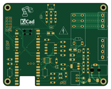
About the Pico IoT thingy PCB
Pico IoT thingy is an open source Raspberry Pi PCB design by mhered, published on GitHub. It is a 4-layer board measuring 95 × 75 mm, with 53 components from 37 distinct parts.
Its main chip is the RaspberryPi_Pico_W, from the Raspberry Pi family. Other key parts include the THVD1406DR, MLX90393ELW-ABA-011-SP and MLX90393ELW-ABA-012-SP. By type, the board carries 20 resistors, 8 capacitors, 7 connectors, 7 diodes, 4 ICs and 3 switches.
It belongs with the iot & wireless and sensors designs in this gallery.
From the project
My notes on the course "PCB design with KiCAD - updated for KiCAD 9" by Dr Peter Dalmaris in Udemy
Design of a Raspberry PICO IoT device on 4-layer PCB with sensors and more. Ref. https://www.youtube.com/watch?v=tCulctQqdhM by morten
Raspberry Pi Pico (W) RS485 / MOD-bus interface DIP-switch for MOD-bus address selection SHT31-DIS high precision temperature and humidity sensor. I used P version (with protective film for reflow) QWIIC connector Reset Button User Button User RGB LED 2x5 pin SPI bus expansion header Power relay (230V - 16A) * Wide range input voltage +8V to 24V DC
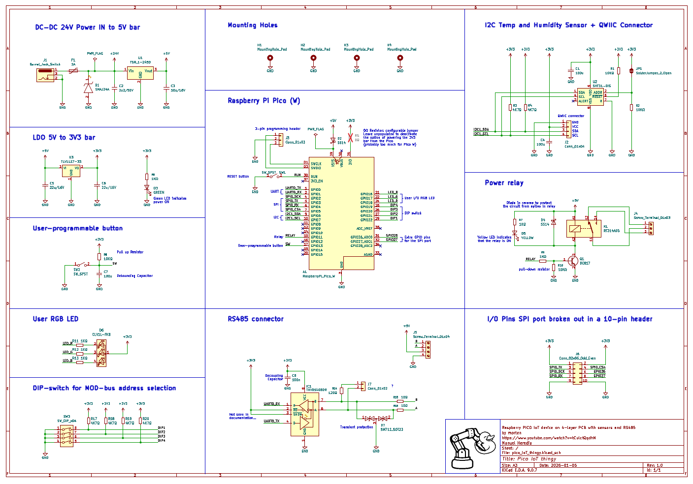
Main components on the Pico IoT thingy
Pico IoT thingy bill of materials (BOM)
53 components, 37 distinct parts — part numbers from the project's BOM.
| Qty | Part | Footprint | Refs |
|---|---|---|---|
| 1 | THVD1406DR | SOIC-8_3.9x4.9mm_P1.27mm | IC1 |
| 1 | MLX90393ELW-ABA-011-SP TSR_1-2450 Melexis | Converter_DCDC_TRACO_TSR-1_THT | U1 |
| 1 | MLX90393ELW-ABA-012-SP SHT31-DIS Melexis | Sensirion_DFN-8-1EP_2.5x2.5mm_P0.5mm_EP1.1x1.7mm | U2 |
| 1 | MLX90393ELW-ABA-012-SP TLV1117-33 Melexis | SOT-223-3_TabPin2 | U3 |
| 1 | RaspberryPi_Pico_W | RaspberryPi_Pico_W_SMD_HandSolder | A1 |
| 1 | BC817 | SOT-23 | Q1 |
| 1 | Barrel_Jack_Switch JST Sales American Inc | BarrelJack_GCT_DCJ200-10-A_Horizontal | J1 |
| 1 | QWIIC | JST_SH_SM04B-SRSS-TB_1x04-1MP_P1.00mm_Horizontal | J2 |
| 1 | Conn_01x03 | PinHeader_1x03_P2.54mm_Vertical | J3 |
| 1 | Screw_Terminal_01x03 | TerminalBlock_MaiXu_MX126-5.0-03P_1x03_P5.00mm | J4 |
| 1 | Screw_Terminal_01x04 | TerminalBlock_MaiXu_MX126-5.0-04P_1x04_P5.00mm | J5 |
| 1 | Conn_02x05_Odd_Even | PinHeader_2x05_P2.54mm_Vertical | J6 |
| 1 | Conn_01x02 | PinHeader_1x02_P2.54mm_Vertical | J7 |
| 1 | 1A | MFSM1002 | F1 |
| 1 | RT314A05 | Relay_SPDT_Schrack-RT1-16A-FormC_RM5mm | K1 |
| 2 | SW_SPST | SW_Tactile_SPST_NO_Straight_CK_PTS636Sx25SMTRLFS | SW1, SW2 |
| 1 | SW_DIP_x04 | 2194MST | SW3 |
| 1 | SMAJ24A | DIOM5127X229N | D1 |
| 2 | SS14 | D_SMA | D2, D4 |
| 1 | GREEN | LED_1206_3216Metric_Pad1.42x1.75mm_HandSolder | D3 |
Show 17 more
| Qty | Part | Footprint | Refs |
|---|---|---|---|
| 1 | YELLOW | LED_1206_3216Metric_Pad1.42x1.75mm_HandSolder | D5 |
| 1 | SM712_SOT23 | SOT-23 | D7 |
| 1 | LED_RGBA | LED_RGB_1210 | D8 |
| 2 | CC0402JRX7R7BB104 100u Yageo | C_1206_3216Metric_Pad1.33x1.80mm_HandSolder | C1, C4 |
| 1 | CC0402JRX7R7BB104 2u2/50V Yageo | C_1206_3216Metric_Pad1.33x1.80mm_HandSolder | C2 |
| 1 | CC0402JRX7R7BB104 10u/16V Yageo | C_1206_3216Metric_Pad1.33x1.80mm_HandSolder | C3 |
| 1 | CC0402JRX7R7BB104 22u/16V Yageo | C_1206_3216Metric_Pad1.33x1.80mm_HandSolder | C5 |
| 1 | 22u/16V | C_1206_3216Metric_Pad1.33x1.80mm_HandSolder | C6 |
| 1 | 100u | C_1206_3216Metric_Pad1.33x1.80mm_HandSolder | C7 |
| 1 | 100n | C_1206_3216Metric_Pad1.33x1.80mm_HandSolder | C8 |
| 2 | RC0402FR-074K7L 10KΩ Yageo | R_1206_3216Metric_Pad1.30x1.75mm_HandSolder | R1, R2 |
| 6 | 4K7Ω | R_1206_3216Metric_Pad1.30x1.75mm_HandSolder | R3, R4, R17, R18, R19, R20 |
| 1 | 0Ω | R_1206_3216Metric_Pad1.30x1.75mm_HandSolder | R5 |
| 6 | 1KΩ | R_1206_3216Metric_Pad1.30x1.75mm_HandSolder | R6, R7, R9, R11, R12, R13 |
| 2 | 10KΩ | R_1206_3216Metric_Pad1.30x1.75mm_HandSolder | R8, R10 |
| 1 | 120Ω | R_1206_3216Metric_Pad1.30x1.75mm_HandSolder | R14 |
| 2 | 10Ω | R_1206_3216Metric_Pad1.30x1.75mm_HandSolder | R15, R16 |
Pico IoT thingy design files
The KiCad project lives in the mhered/KiCAD_udemy_course repository on GitHub; these links point at the commit this page was built from.
Pico IoT thingy: common questions
What microcontroller does the Pico IoT thingy use?
The Pico IoT thingy is built around the RaspberryPi_Pico_W, from the Raspberry Pi family.
How big is the Pico IoT thingy PCB?
The Pico IoT thingy measures 95 × 75 mm, has 4 copper layers and is 1.6 mm thick.
How many components are on the Pico IoT thingy?
53 components, from 37 distinct parts, with part numbers taken from the project's own BOM. The full bill of materials is listed on this page.
Where can I download the Pico IoT thingy design files?
From the mhered/KiCAD_udemy_course repository on GitHub, which has the KiCad layout, the schematic and the BOM; the links under Design files point to each one.
Can I use the Pico IoT thingy design in my own project?
The repository has no license, so all rights stay with mhered. Use it as a reference, and ask the author before reusing the design.
Can I test firmware for the Pico IoT thingy without the hardware?
Yes. HardLabs builds a simulation of the board from its netlist and BOM, so you can run and debug Raspberry Pi firmware against it before you order a PCB.
More boards in KiCAD_udemy_course
MSPM0
68 × 33 mm36 parts2LNo license2- schematic only · 24 partsAVR/Arduino
${project name}
24 parts2LNo license2 
Kinect
90 × 25.1 mm20 parts2LNo license2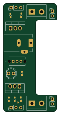
Breadboard power supply v1
27.8 × 56.4 mm17 parts2LNo license2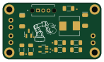
Tiny solar supply
36.8 × 20.8 mm16 parts2LNo license2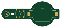
LED Torch
61.1 × 26.3 mm4 parts2LNo license2
Similar boards
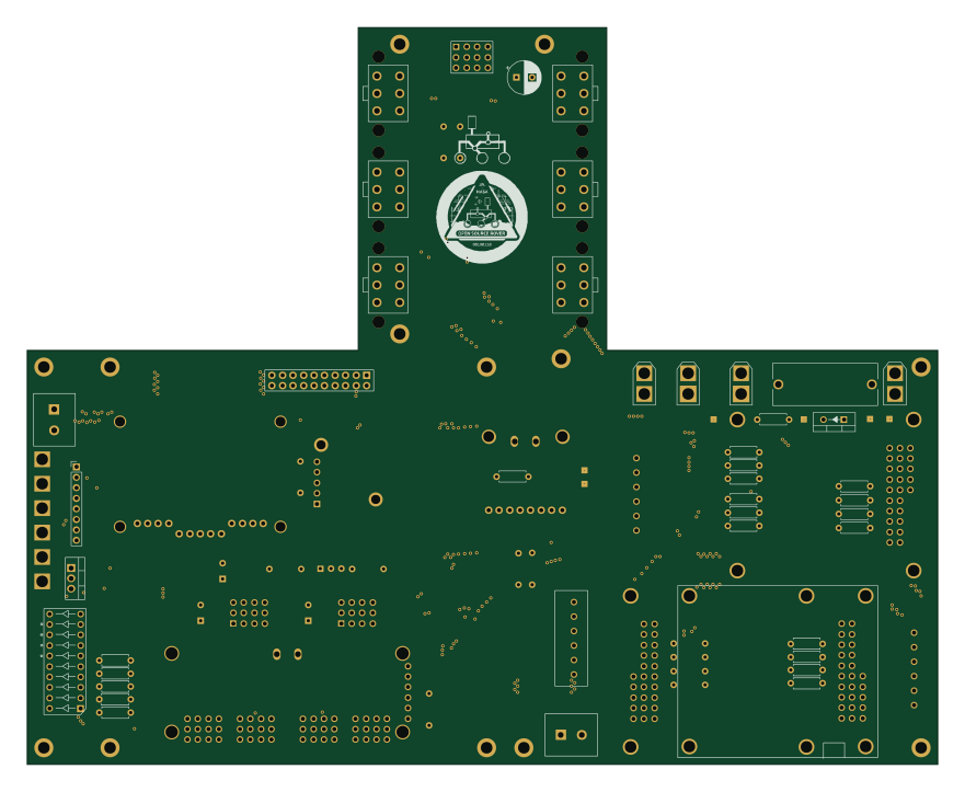 Raspberry Pi
Open source rover
nasa-jpl
220 × 178 mm144 parts2LApache-2.09.7k Raspberry Pi
SPIRIT
SPIRIT-org
82 × 155 mm130 parts6LCERN-OHL-S-2.01.3k Raspberry Pi
CM5RevEng
schlae
55 × 40 mm417 parts10LNo license1.0k Raspberry Pi
Haxo hw
cardonabits
102.4 × 211.3 mm38 parts2LCustom license672 Raspberry Pi
PowerBook
BlueSCSI
74.5 × 56.3 mm78 parts2LGPL-3.0449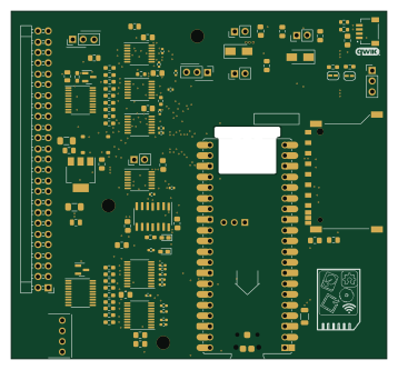 Raspberry Pi
Desktop 50 Pin TopConn
89.2 × 82.6 mm103 parts2LGPL-3.0449