
Joytester

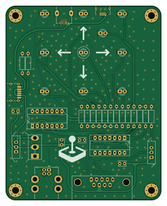
About the Joytester PCB
Joytester is an open source PCB design by mistepien, published on GitHub under the GPL-3.0 license. It is a 2-layer board measuring 80 × 100 mm, with 38 components from 23 distinct parts.
Other key parts include the 4070 and 74HC86. By type, the board carries 15 resistors, 10 diodes, 4 connectors, 4 capacitors, 3 switches and 2 ICs.
It belongs with the retro computing designs in this gallery.
From the project
Joytester for Atari-like+ joysticks
Joytester for testing Atari-like joysticks -- tests also FIRE2 nd FIRE3 in C64 and Amiga/Atari mode.
More about Amiga/Atari and C64 modes: schematic of universal joystick.
You can use the gerber file to order the PCB.
Here you have the schematic file to find out how does it work.
BOM: | Qty | Reference(s) | Description | |-----|--------------|-------------| |10 | D1, D2, D3, D4, D5, D6, D7, D8, D9, D10 | LEDs 3mm | |10 | R1, R2, R3, R4, R5, R6, R7, R8, R9, R10 | resisors for D1...D10 | |3 | R11, R12, R13 | 10KΩ pull-up/pull-down resistors | | 2 | R14, R15 | 5K1Ω resistors for J3 USB C…
Main components on the Joytester
Joytester bill of materials (BOM)
38 components, 23 distinct parts — part numbers from the project's BOM.
| Qty | Part | Footprint | Refs |
|---|---|---|---|
| 1 | 4070 | DIP-14_W7.62mm_Socket_LongPads | U1 |
| 1 | 74HC86 | DIP-14_W7.62mm_Socket_LongPads | U2 |
| 1 | USB_B | USB_B_Lumberg_2411_02_Horizontal_Oval_Versatile | J2 |
| 1 | USB_C_RECEPTACLE_POWERONLY_6P USB_C_Receptacle_PowerOnly_6P | GCT_USB4125-GF-A | J3 |
| 1 | USB_B_Mini | UBM5BRDM144DLFSNL | J4 |
| 1 | USB_B_Micro | USB_Micro-B_Amphenol_10118194_Horizontal | J5 |
| 1 | C64MODESW | E-Switch-EG1218-Manufacturer_Recommended_Oval | SW1 |
| 1 | POWER | E-Switch-EG1218-Manufacturer_Recommended_Oval | SW2 |
| 1 | POWER | 100SP1T1B4M2QE | SW3 |
| 1 | C64 | LED_D3.0mm_Oval | D1 |
| 1 | RIGHT | LED_D3.0mm_Oval | D2 |
| 1 | UP | LED_D3.0mm_Oval | D3 |
| 1 | DOWN | LED_D3.0mm_Oval | D4 |
| 1 | FIRE1 | LED_D3.0mm_Oval | D5 |
| 1 | STATUS | LED_D3.0mm_Oval | D6 |
| 1 | LEFT | LED_D3.0mm_Oval | D7 |
| 1 | FIRE2 | LED_D3.0mm_Oval | D8 |
| 1 | FIRE3 | LED_D3.0mm_Oval | D9 |
| 1 | AMIGA | LED_D3.0mm_Oval | D10 |
| 4 | 100NF 100nF | C_Disc_D3.8mm_W2.6mm_P2.50mm | C1, C2, C3, C4 |
Show 3 more
| Qty | Part | Footprint | Refs |
|---|---|---|---|
| 10 | RxΩ | R_Axial_DIN0207_L6.3mm_D2.5mm_P10.16mm_Horizontal_Oval | R1, R2, R3, R4, R5, R6, R7, R8 +2 |
| 3 | R10KΩ | R_Axial_DIN0207_L6.3mm_D2.5mm_P10.16mm_Horizontal_Oval | R11, R12, R13 |
| 2 | R5K1Ω | R_Axial_DIN0207_L6.3mm_D2.5mm_P10.16mm_Horizontal_Oval | R14, R15 |
Joytester design files
The KiCad project lives in the mistepien/joytester repository on GitHub; these links point at the commit this page was built from.
- Layoutjoytester.kicad_pcb
- Schematicjoytester.kicad_sch
- BOMproduction/bom.csv
Joytester: common questions
How big is the Joytester PCB?
The Joytester measures 80 × 100 mm, has 2 copper layers and is 1.6 mm thick.
How many components are on the Joytester?
38 components, from 23 distinct parts, with part numbers taken from the project's own BOM. The full bill of materials is listed on this page.
Where can I download the Joytester design files?
From the mistepien/joytester repository on GitHub, which has the KiCad layout, the schematic and the BOM; the links under Design files point to each one.
Can I use the Joytester design in my own project?
Yes, under the terms of its GPL-3.0 license, which mistepien chose for the repository.
Similar boards
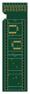
Amiga External
hoglet67
21.9 × 76.7 mm6 parts2LGPL-3.01.0k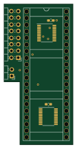
Atari pickup
26.4 × 53.9 mm7 parts2LGPL-3.01.0k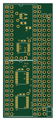
Deniseadapter
26.7 × 62.2 mm16 parts2LGPL-3.01.0k
Analog
53.9 × 23.2 mm33 parts2LGPL-3.01.0k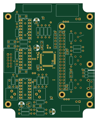
Rgb to hdmi
77 × 97 mm67 parts2LGPL-3.01.0k
Buffer
53.9 × 23.2 mm13 parts2LGPL-3.01.0k