
Controller-Electrical-Schematics

About the Controller-Electrical-Schematics PCB
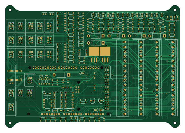
Controller-Electrical-Schematics is an open source AVR/Arduino PCB design by mk4-dd, published on GitHub. It is a 4-layer board measuring 181.7 × 127.5 mm, with 216 components from 34 distinct parts.
Its main chip is the ARDUINO_MEGA_SHIELD, from the AVR/Arduino family. Other key parts include the NCS3S1205SC, LCA715, CD4013B, LM358 and SN74HC595N. By type, the board carries 114 resistors, 42 transistors, 24 connectors, 18 capacitors, 8 ICs and 7 diodes.
From the project
This repo is a part of the Hitchco MK4 project. You can read more about the project here.
This repo is a part of the Hitchco MK4 project. You can read more about the project here.
The PCB was designed in KiCAD and manufactured by OSHPark. It's essentially a giant shield for an Arduino Mega that drives many Power MOSFET devices, and conditions the inputs from the car. It also has many connectors for illuminated pushbuttons.
Many through-hole components were used for ease of assembly, and overall design simplicity.

Main components on the Controller-Electrical-Schematics
Controller-Electrical-Schematics bill of materials (BOM)
216 components, 34 distinct parts.
| Qty | Part | Footprint | Refs |
|---|---|---|---|
| 1 | NCS3S1205SC | NCS3S1205SC | U1 |
| 1 | LCA715 | DIP-6_W7.62mm_Socket | U2 |
| 1 | CD4013B | DIP-14_W7.62mm_Socket | U3 |
| 1 | LM358 | DIP-8_W7.62mm | U4 |
| 2 | SN74HC595N | DIP-16_W7.62mm_Socket | U5, U6 |
| 1 | CD74HC4067 | SOIC-24W_7.5x15.4mm_Pitch1.27mm | U7 |
| 1 | LM339 | DIP-14_W7.62mm_Socket | U8 |
| 18 | 2N3904 | TO-92_Inline_Narrow_Oval | Q1, Q4, Q6, Q9, Q11, Q15, Q17, Q19 +10 |
| 16 | NTB5605PT4G | TO-263-3_TabPin2 | Q2, Q3, Q5, Q8, Q10, Q14, Q16, Q18 +8 |
| 6 | FQB30N06LTM | TO-263-3_TabPin2 | Q7, Q12, Q13, Q20, Q31, Q32 |
| 2 | BSS138 | SOT-23 | Q41, Q42 |
| 4 | Screw_Terminal_01x16 | TerminalBlock_Phoenix_45Deg_MKDS1.5-16pol | J1, J4, J8, J13 |
| 20 | Conn_02x03_Counter_Clockwise | Shroud_Socket_Strip_Straight_2x03_Pitch2.54mm | J2, J3, J5, J6, J7, J9, J10, J11 +12 |
| 1 | Jumper | D_DO-201AD_P15.24mm_Horizontal | JP1 |
| 1 | 10KΩ | Potentiometer_Trimmer_Bourns_PV36W | RV1 |
| 1 | ARDUINO_MEGA_SHIELD | ARDUINO_MEGA_SHIELD | SHIELD1 |
| 5 | SB5100E-G | D_DO-201AD_P15.24mm_Horizontal | D2, D3, D7, D8, D11 |
| 2 | WP7113ID | LED_D5.0mm | D4, D5 |
| 16 | 0.1uF | C_Rect_L5.08mm_W3.175mm_P2.54mm | C1, C2, C3, C4, C7, C8, C9, C10 +8 |
| 2 | 0.01uF | C_Rect_L5.08mm_W3.175mm_P2.54mm | C5, C6 |
Show 14 more
| Qty | Part | Footprint | Refs |
|---|---|---|---|
| 56 | 10KΩ | R_Axial_DIN0204_L3.6mm_D1.6mm_P5.08mm_Horizontal | R1, R8, R9, R19, R20, R27, R29, R30 +48 |
| 22 | 1KΩ | R_Axial_DIN0204_L3.6mm_D1.6mm_P5.08mm_Horizontal | R2, R3, R4, R5, R7, R11, R12, R28 +14 |
| 1 | 560Ω | R_Axial_DIN0204_L3.6mm_D1.6mm_P5.08mm_Horizontal | R6 |
| 5 | 100KΩ | R_Axial_DIN0204_L3.6mm_D1.6mm_P5.08mm_Horizontal | R13, R17, R23, R25, R118 |
| 4 | 51KΩ | R_Axial_DIN0204_L3.6mm_D1.6mm_P5.08mm_Horizontal | R14, R24, R26, R119 |
| 1 | 43Ω | R_Axial_DIN0204_L3.6mm_D1.6mm_P5.08mm_Horizontal | R15 |
| 1 | 47Ω | R_Axial_DIN0204_L3.6mm_D1.6mm_P5.08mm_Horizontal | R16 |
| 1 | 105KΩ | R_Axial_DIN0204_L3.6mm_D1.6mm_P5.08mm_Horizontal | R18 |
| 2 | 4.3KΩ | R_Axial_DIN0204_L3.6mm_D1.6mm_P5.08mm_Horizontal | R21, R22 |
| 1 | 5.1KΩ | R_Axial_DIN0204_L3.6mm_D1.6mm_P5.08mm_Horizontal | R34 |
| 2 | 330Ω | R_Axial_DIN0204_L3.6mm_D1.6mm_P5.08mm_Horizontal | R41, R45 |
| 15 | 10K | R_Axial_DIN0204_L3.6mm_D1.6mm_P5.08mm_Horizontal | R46, R47, R48, R49, R50, R51, R52, R53 +7 |
| 2 | 3.3KΩ | R_Axial_DIN0204_L3.6mm_D1.6mm_P5.08mm_Horizontal | R78, R79 |
| 1 | 15KΩ | R_Axial_DIN0204_L3.6mm_D1.6mm_P5.08mm_Horizontal | R86 |
Controller-Electrical-Schematics design files
The KiCad project lives in the mk4-dd/Controller-Electrical-Schematics repository on GitHub; these links point at the commit this page was built from.
Controller-Electrical-Schematics: common questions
What microcontroller does the Controller-Electrical-Schematics use?
The Controller-Electrical-Schematics is built around the ARDUINO_MEGA_SHIELD, from the AVR/Arduino family.
How big is the Controller-Electrical-Schematics PCB?
The Controller-Electrical-Schematics measures 181.7 × 127.5 mm, has 4 copper layers and is 1.6 mm thick.
How many components are on the Controller-Electrical-Schematics?
216 components, from 34 distinct parts. The full bill of materials is listed on this page.
Where can I download the Controller-Electrical-Schematics design files?
From the mk4-dd/Controller-Electrical-Schematics repository on GitHub, which has the KiCad layout; the links under Design files point to each one.
Can I use the Controller-Electrical-Schematics design in my own project?
The repository has no license, so all rights stay with mk4-dd. Use it as a reference, and ask the author before reusing the design.
Can I test firmware for the Controller-Electrical-Schematics without the hardware?
Yes. HardLabs builds a simulation of the board from its netlist and BOM, so you can run and debug AVR/Arduino firmware against it before you order a PCB.
Similar boards
 AVR/Arduino
Magspoof
samyk
35 × 29 mm11 parts2LNo license4.2k AVR/Arduino
Redox keyboard
mattdibi
162.2 × 126.5 mm77 parts2LMIT2.0k AVR/Arduino
Labrador
espotek-org
36.8 × 34.7 mm75 parts2LNo license1.2k AVR/Arduino
ModuleV450
stuartpittaway
30 × 61.4 mm39 parts2LCC-BY-NC-4.01.1k AVR/Arduino
V4
30 × 50 mm38 parts2LCC-BY-NC-4.01.1k AVR/Arduino
Discipline
coseyfannitutti
304.9 × 122.8 mm170 parts2LCC-BY-NC-4.01.0k