
88 open source boards using the LM339
Real designs built with the LM339, from public GitHub projects: a quick way to see how others power, decouple and connect it. Each board comes with its KiCad files, full parts list and a render — and you can simulate its firmware on HardLabs.
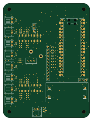 Raspberry Pi
Phased
Neumi
75 × 100 mm71 parts2LNo license507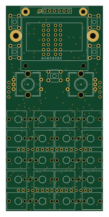
Analog rev3
PaulStoffregen
50.8 × 108 mm200 parts2LNo license160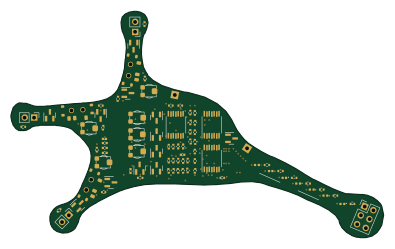
Lu.i neuron
giant-axon
98.5 × 59.8 mm88 parts2LCERN-OHL-S-2.072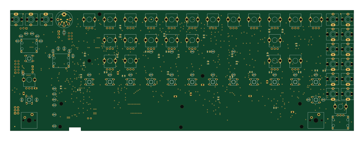 AVR/Arduino
TR-808-Clone
minisystem
300 × 105 mm1058 parts2LNo license67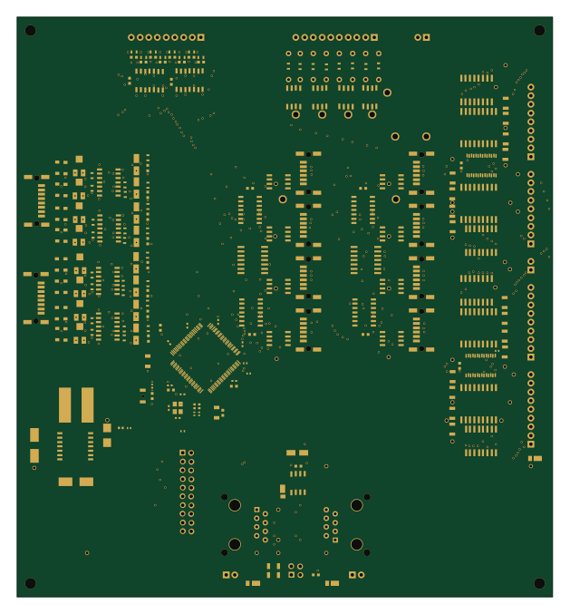 NXP
LPC176x MultiFunction
RobertPHeller
156.2 × 168.9 mm223 parts2LCC-BY-4.024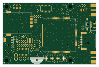 AVR/Arduino
Rvi v2x hardware
PDXostc
85 × 56 mm186 parts2LMPL-2.09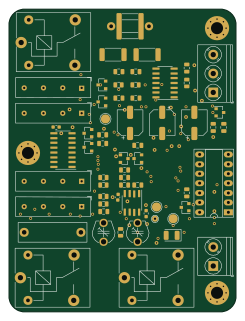
Keithley1950
openscopeproject
60 × 80 mm83 parts2LCERN-OHL-1.29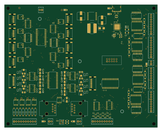 ESP32
ESP32-S3-MegaMultiFunction
165.1 × 132.1 mm238 parts2LCC-BY-4.03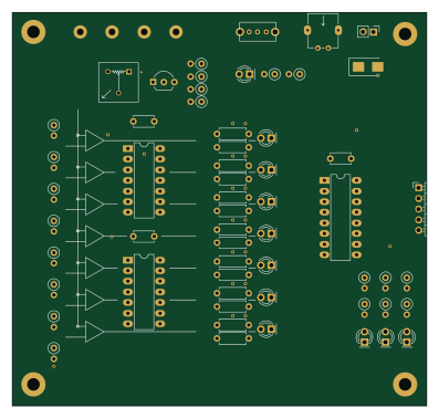
Km discrete adc
KnoxMakers
99.1 × 94 mm66 parts2LNo license3
DMH Output PCB 1
DeMarco
48 × 175 mm263 parts2LCC0-1.02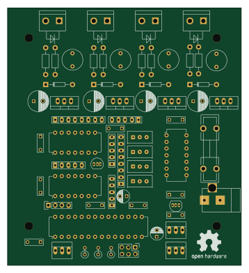 AVR/Arduino
Led controller
astoeckel
88.9 × 97.8 mm62 parts2LCERN-OHL-1.22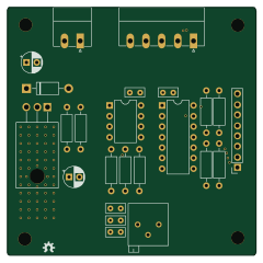
DMX Demonstrator - Analog IO PWM (DMX-IO4)
SparkyBobo
60 × 60 mm24 parts2LGPL-3.02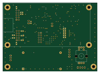
K PA Protec
F6ITU
102.5 × 75 mm83 parts2LNo license1
BMS
Wierdwizard2587
179 × 44 mm64 parts2LNo license1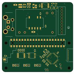 Raspberry Pi
Piweather
pluggee
65 × 64 mm58 parts4LMIT1- schematic only · 98 parts
Meyer Sound 24.033.003 Amp RevEng
LeoDJ
98 partsNo license1 - schematic only · 54 parts
Cx22
owen-rp2a03
54 partsNo license1 - schematic only · 33 parts
TrailerDiagnosticSystem
patricecouillard-code
33 partsNo license1 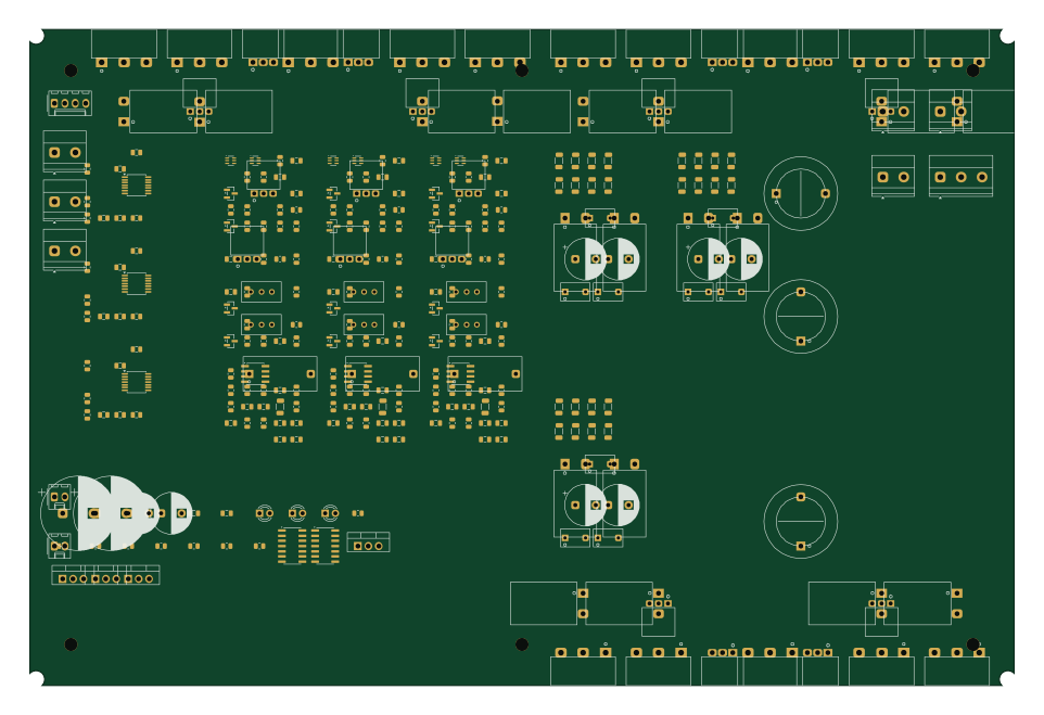
Front-Stage-3-Channel-AB
bunny-assassin
240 × 160 mm318 parts4LNo license0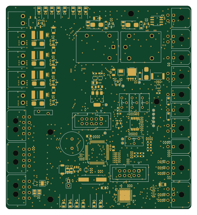 STM32
PROJ500 - Power Distribution Board
AislingBee
99.1 × 108.6 mm297 parts2LNo license0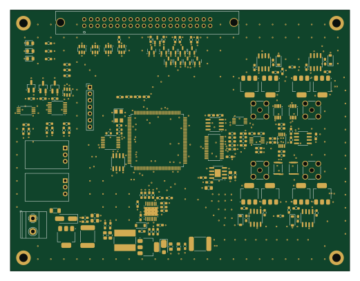 FPGA
NadDeska
AntoninCerny
130 × 100 mm292 parts4LNo license0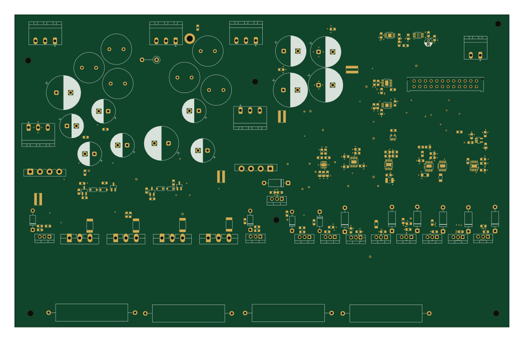
Laser driver v3 Power
scular-HCC
261.3 × 165.2 mm273 parts2LCustom license0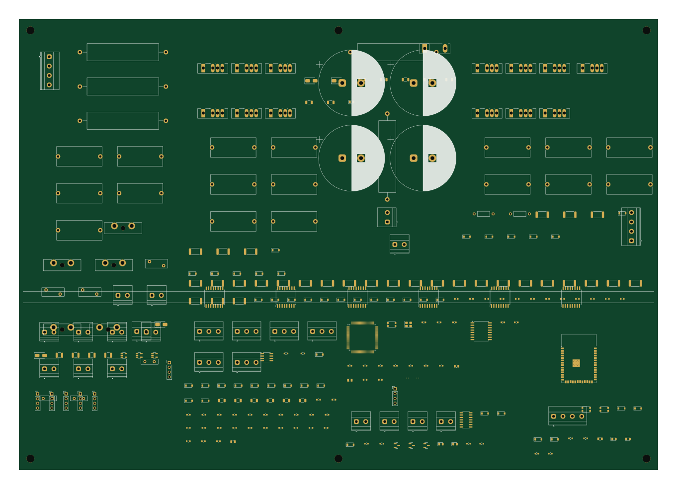 ESP32
Back To Back-Convertidor-Bidireccional-AC-AC-
FernandoVB01
340 × 240 mm239 parts4LNo license0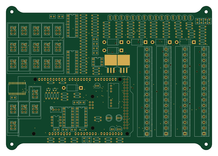 AVR/Arduino
Controller-Electrical-Schematics
mk4-dd
181.7 × 127.5 mm216 parts4LNo license0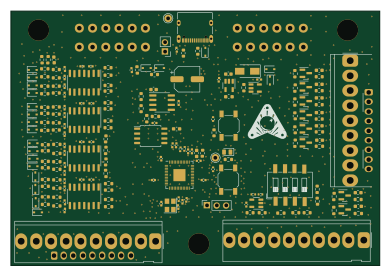 RP2040/RP2350
Hardware IO 16x8 matrix
PPUC
97.6 × 67.3 mm202 parts2LTAPR-OHL-1.00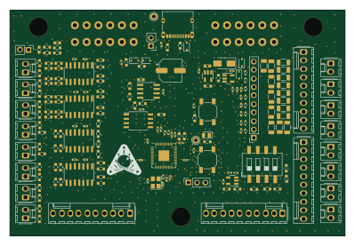 RP2040/RP2350
Hardware Opto 16
99.7 × 67.3 mm200 parts2LTAPR-OHL-1.00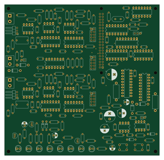 Raspberry Pi
Vinyl adc rev d
MadsRudolph
140 × 136 mm177 parts4LNo license0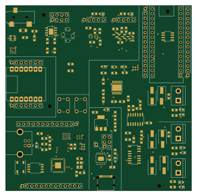 RP2040/RP2350
XDuinoRail-Debug
chatelao
99.1 × 99 mm147 parts2LAGPL-3.00 STM32
Pride Badge
aziraphale
65.2 × 72.2 mm128 parts2LNo license0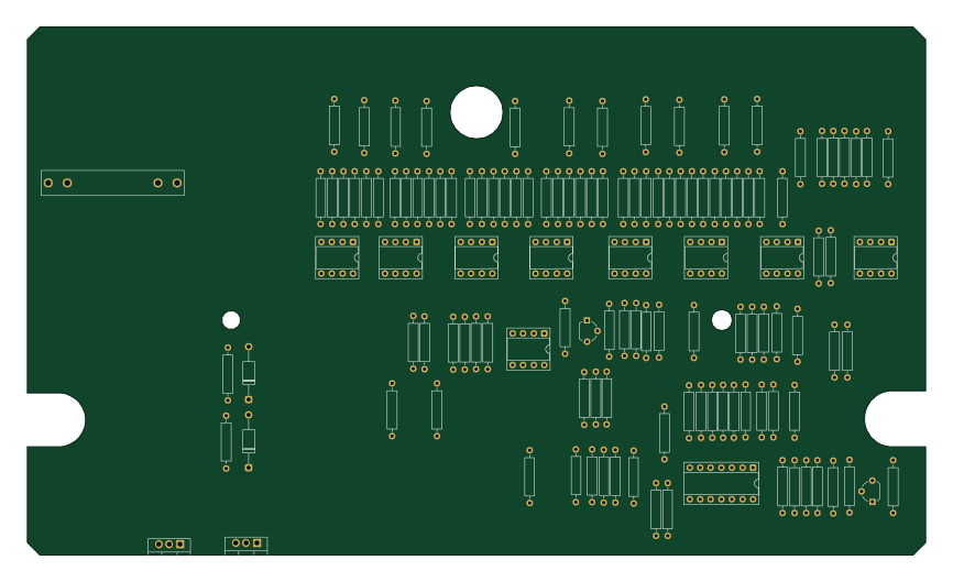
Rockman EQ
rtapson
216 × 127 mm128 parts2LCC0-1.00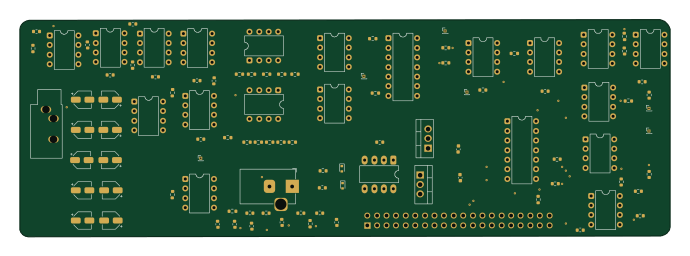
MIS
nmahadevan12
172.3 × 57.5 mm103 parts4LNo license0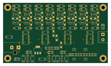
Logic probe
sjm42
95 × 55 mm99 parts2LApache-2.00
BSPD
Nomalah
53.3 × 27.9 mm71 parts4LNo license0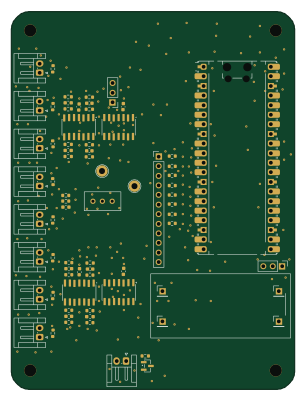 Raspberry Pi
Phased
kskwon02
75 × 100 mm71 parts2LNo license0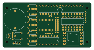
TriBit-Lux
XEMACS-666
80 × 41 mm57 parts2LNo license0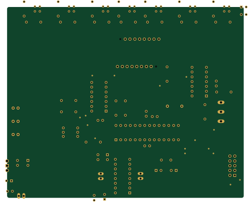 AVR/Arduino
LineFollower
uHappyLogic
125 × 101 mm53 partsGPL-2.00
How designs wire the LM339
Read from the KiCad layouts of 57 open source designs, one per repository: what each pin of the LM339 connects to, and the resistors, capacitors and other passives placed on it.
- The V- pin is tied to GND on 46 of 57 designs (-12V on 8, a signal on 3).
- The + pins have a series resistor on 36 of 57 designs, most often 10 kΩ (then 100 kΩ).
- The - pins have a series resistor on 32 of 57 designs, most often 100 kΩ (then 1 kΩ).
- Pin 2 has a pull-up to 3.3V on 29 of 57 designs, most often 10 kΩ (then 4.7 kΩ).
| Pin | Connected to | Parts on the pin |
|---|---|---|
| Pin 1 | Connected to: Signal 93% |
|
| Pin 2 | Connected to: Signal 96% |
|
| V+pin 3 | Connected to: 5V 86% |
|
| -pin 4, 6, 8, 10 | Connected to: Signal 81% |
|
| +pin 5, 7, 9, 11 | Connected to: Signal 86% |
|
| V-pin 12 | Connected to: GND 81% | — |
| Pin 13 | Connected to: Signal 86% |
|
| Pin 14 | Connected to: Signal 86% |
|
Connections count pins, parts count designs; values in brackets are how many parts had that value. Designs read include Phased by Neumi, Analog rev3 by PaulStoffregen, Lu.i neuron pcb by giant-axon and TR-808-Clone by minisystem.
The LM339 in open source designs
The gallery holds 88 open source boards using the LM339 from 66 GitHub repositories; a typical one measures about 98.5 × 99 mm and carries around 87 components.
80% are two-layer designs, the rest use four layers or more, and 42% carry an open source license.
The most starred is Triple adapter by rene-dev.
Parts used alongside the LM339
Microcontrollers on boards using the LM339
What boards using the LM339 are built for
LM339: common questions
Where can I find a LM339 reference design?
Each of the 88 boards on this page is a real design using the LM339. Open one to see how it is wired up, with the full BOM, a render of the layout and links to its KiCad files.
How is the LM339 V- pin connected?
The V- pin is tied to GND on 46 of 57 designs (-12V on 8, a signal on 3). Counted from the KiCad layouts of 57 open source designs using the LM339.
What resistor goes on the LM339 + pin?
The + pins have a series resistor on 36 of 57 designs, most often 10 kΩ (then 100 kΩ). Counted from the KiCad layouts of 57 open source designs using the LM339.
What resistor goes on the LM339 - pin?
The - pins have a series resistor on 32 of 57 designs, most often 100 kΩ (then 1 kΩ). Counted from the KiCad layouts of 57 open source designs using the LM339.
What parts are used alongside the LM339?
The LM358, NE5532, MCP6004, TL072 and USBLC6-2SC6 appear in the most repositories here.
Which microcontrollers do boards using the LM339 use?
Most are built on AVR/Arduino (13), ESP32 (11), Raspberry Pi (6) and RP2040/RP2350 (5).
How big is a typical board using the LM339?
The median is 98.5 × 99 mm, and 80% are two-layer designs.
What is the most popular open source board using the LM339?
By GitHub stars, Triple adapter by rene-dev, with 979 stars.
Can I simulate one of these boards using the LM339 before building it?
Yes. HardLabs turns a board's netlist and BOM into a working simulation, so you can boot and test firmware against it with no hardware on your desk.