
BRIDGEADC01

About the BRIDGEADC01 PCB
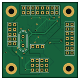
BRIDGEADC01 is an open source PCB design by mlab-modules, published on GitHub under the GPL-3.0 license. It is a 2-layer board measuring 40.1 × 40.1 mm, with 40 components from 32 distinct parts.
Other key parts include the MIC4426 and AD7730. By type, the board carries 23 connectors, 7 capacitors, 3 resistors, 2 ICs, 2 diodes and 2 inductors.
It belongs with the sensors designs in this gallery.
From the project
Strain Gauges analog front end and ADC
The module is a complete analog front end for weigh-scale and pressure measurement applications. The device accepts low-level signals directly from a bridge transducer and outputs a serialdigital word on SPI interface.Exitation voltage could be generated by module itself. Exitation signal is synchronous with internal signal sampling.

Main components on the BRIDGEADC01
BRIDGEADC01 bill of materials (BOM)
40 components, 32 distinct parts — part numbers from the project's BOM.
| Qty | Part | Footprint | Refs |
|---|---|---|---|
| 1 | MIC4426 | SOIC-8_3.9x4.9mm_Pitch1.27mm | U1 |
| 1 | AD7730 | TSSOP-24_4.4x7.8mm_Pitch0.65mm | U2 |
| 1 | 4.9152 MHz | Crystal_HC49-U_Vertical | Y1 |
| 1 | 3÷5V | Straight_2x03 | J1 |
| 1 | ACX | Straight_1x02 | J2 |
| 1 | ~{ACX} | Straight_1x02 | J3 |
| 1 | AIN1+ | Straight_1x02 | J4 |
| 1 | AIN1- | Straight_1x02 | J5 |
| 1 | AIN2+ | Straight_1x02 | J6 |
| 1 | AIN2- | Straight_1x02 | J7 |
| 1 | REFIN- | Straight_1x02 | J8 |
| 1 | REFIN+ | Straight_1x02 | J9 |
| 1 | POL | Straight_1x03 | J10 |
| 1 | ~{RESET} | Straight_1x02 | J11 |
| 1 | ~{SYNC} | Straight_1x02 | J12 |
| 1 | ~{RDY} | Straight_1x02 | J13 |
| 1 | ~{CS} | Straight_1x02 | J14 |
| 1 | SCLK | Straight_1x02 | J15 |
| 1 | DIN | Straight_1x02 | J16 |
| 1 | DOUT | Straight_1x02 | J17 |
Show 12 more
| Qty | Part | Footprint | Refs |
|---|---|---|---|
| 1 | ~{STANDBY} | Straight_1x02 | J18 |
| 1 | +5V | Straight_2x03 | J19 |
| 1 | MCLKIN | Straight_1x02 | J20 |
| 1 | MCLKOUT | Straight_1x02 | J21 |
| 1 | VAA | Straight_1x02 | J22 |
| 1 | GND | Straight_1x02 | J23 |
| 2 | M4 | SMA_Standard | D1, D2 |
| 2 | BLM21PG300SN1D | C_0805 | L1, L2 |
| 2 | 10uF | TantalC_SizeB_EIA-3528_Reflow | C1, C5 |
| 4 | 100nF | C_0805 | C2, C3, C6, C7 |
| 1 | 10UF 10uF | TantalC_SizeB_EIA-3528_Reflow | C4 |
| 3 | 10k | R_0805 | R1, R2, R3 |
BRIDGEADC01 design files
The KiCad project lives in the mlab-modules/BRIDGEADC01 repository on GitHub; these links point at the commit this page was built from.
BRIDGEADC01: common questions
How big is the BRIDGEADC01 PCB?
The BRIDGEADC01 measures 40.1 × 40.1 mm, has 2 copper layers and is 1.6 mm thick.
How many components are on the BRIDGEADC01?
40 components, from 32 distinct parts, with part numbers taken from the project's own BOM. The full bill of materials is listed on this page.
Where can I download the BRIDGEADC01 design files?
From the mlab-modules/BRIDGEADC01 repository on GitHub, which has the KiCad layout, the schematic and the BOM; the links under Design files point to each one.
Can I use the BRIDGEADC01 design in my own project?
Yes, under the terms of its GPL-3.0 license, which mlab-modules chose for the repository.
Similar boards

Sensor smd
scottbez1
40 × 20 mm5 parts2LApache-2.04.2k
Sensors
StuckAtPrototype
15.2 × 9 mm14 parts4LApache-2.03.8k
Microphone
Mentra-Community
5.5 × 6.1 mm6 parts2LMIT1.2k
TemperaturePCB PANEL
stuartpittaway
116 × 75.5 mm178 parts2LCC-BY-NC-4.01.1k
Pots
shanteacontrols
390 × 93 mm75 parts2LApache-2.0956
ButtonsLEDs
390 × 37 mm82 parts2LApache-2.0956