
USBSDREADER01

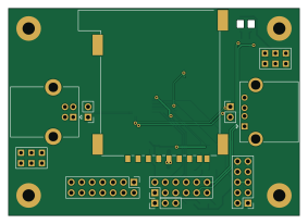
About the USBSDREADER01 PCB
USBSDREADER01 is an open source PCB design by mlab-modules, published on GitHub. It is a 2-layer board measuring 70.6 × 50.3 mm, with 43 components from 23 distinct parts.
Other key parts include the MAX14502AETL+ and TS5A4594. By type, the board carries 13 resistors, 11 connectors, 10 capacitors, 4 diodes, 2 ICs and 2 transistors.
It belongs with the usb & debug tools and power & battery designs in this gallery.
From the project
USB to SD Card Reader module featuring MAX14502AETL, supports USB 2.0 and SDHC cards.
2. USB Connection: - Connect the USB data lines (D+ and D-) to the corresponding pins on the module. - Use the USBB and USBA connectors for input and output respectively.
3. SD Card Connection: - Connect the SD card signals (CMD, CLK, DAT0-3) to the corresponding pins on the module. - Ensure proper insertion and alignment of the SD card.
4. I2C Configuration: - If I2C control is needed, connect the I2C_SEL, SCL, and SDA pins appropriately. - Configure the I2C address using the ADD pin.
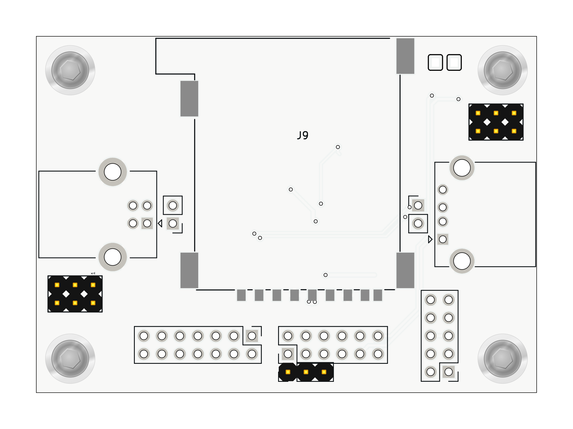
Main components on the USBSDREADER01
USBSDREADER01 bill of materials (BOM)
43 components, 23 distinct parts — part numbers from the project's BOM.
| Qty | Part | Footprint | Refs |
|---|---|---|---|
| 1 | MAX14502AETL+ | QFN40P500X500X80-41N | IC1 |
| 1 | TS5A4594 | SOT-23-5 | U1 |
| 2 | NPN | SOT-23-3 | Q1, Q2 |
| 1 | 3.3V | Straight_2x03 | J1 |
| 1 | USB_B | USB_B_Lumberg_2411_02_Horizontal | J2 |
| 1 | USB_A | USB_A_CONNFLY_DS1095-WNR0 | J3 |
| 1 | VBUS | Straight_2x03 | J4 |
| 1 | HEADER_2X07_PARALLEL HEADER_2x07_PARALLEL | PinHeader_2x07_P2.54mm_Vertical | J5 |
| 1 | HEADER_2X05_PARALLEL HEADER_2x05_PARALLEL | PinHeader_2x05_P2.54mm_Vertical | J6 |
| 1 | HEADER_2X04_PARALLEL HEADER_2x04_PARALLEL | PinHeader_2x06_P2.54mm_Vertical | J7 |
| 1 | HEADER_1X02 HEADER_1x02 | PinHeader_1x03_P2.54mm_Vertical | J8 |
| 1 | SD_CARD-FPS009-4200-0 SD_Card-FPS009-4200-0 | FPS009-4200-0 | J9 |
| 2 | HEADER_1x02 | PinHeader_1x02_P2.54mm_Vertical | J10, J11 |
| 2 | BZV55C-5,6V | D_SMA | D1, D2 |
| 2 | LED | LED_1206_mill | D3, D4 |
| 1 | 1UH 1uH | L_1008_2520Metric | L1 |
| 2 | 10uF | C_0805_2012Metric | C1, C9 |
| 2 | 100nF | C_0805_2012Metric | C2, C10 |
| 5 | C_Small | C_0805_2012Metric | C3, C4, C5, C6, C7 |
| 1 | 10UF 10uF | C_0805_2012Metric | C8 |
Show 3 more
| Qty | Part | Footprint | Refs |
|---|---|---|---|
| 1 | 6.19K 6.19k | R_0805_2012Metric | R1 |
| 6 | 10k | R_0805_2012Metric | R2, R3, R4, R5, R12, R13 |
| 6 | R_Small | R_0805_2012Metric | R6, R7, R8, R9, R10, R11 |
USBSDREADER01 design files
The KiCad project lives in the mlab-modules/USBSDREADER01 repository on GitHub; these links point at the commit this page was built from.
USBSDREADER01: common questions
How big is the USBSDREADER01 PCB?
The USBSDREADER01 measures 70.6 × 50.3 mm, has 2 copper layers and is 1.6 mm thick.
How many components are on the USBSDREADER01?
43 components, from 23 distinct parts, with part numbers taken from the project's own BOM. The full bill of materials is listed on this page.
Where can I download the USBSDREADER01 design files?
From the mlab-modules/USBSDREADER01 repository on GitHub, which has the KiCad layout, the schematic and the BOM; the links under Design files point to each one.
Can I use the USBSDREADER01 design in my own project?
The repository has no license, so all rights stay with mlab-modules. Use it as a reference, and ask the author before reusing the design.
Similar boards

EinkPDA screen
TalismanDesign
95 × 54 mm27 parts2LApache-2.02.0k
Stack chan
stack-chan
50 × 50 mm33 parts2LApache-2.01.7k
Display Carrier
AxxAxx
35.6 × 58.2 mm5 parts2LGPL-3.01.7k
ProgrammingAdapter
stuartpittaway
10.5 × 83 mm3 parts2LCC-BY-NC-4.01.1k
TemperaturePCB PANEL
116 × 75.5 mm178 parts2LCC-BY-NC-4.01.1k
Module 16S PassiveBalanceAddOn
61 × 74 mm86 parts2LCC-BY-NC-4.01.1k