
CAXX-Motor-Driver-PCB

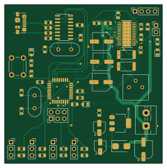
About the CAXX-Motor-Driver-PCB
CAXX-Motor-Driver-PCB is an open source AVR/Arduino PCB design by Mohammed-Emad-2004, published on GitHub. It is a 4-layer board measuring 60 × 60.5 mm, with 61 components from 31 distinct parts.
Its main chip is the ATmega328P-A, from the AVR/Arduino family. Other key parts include the AMS1117-5.0, CH340G and DRV8825. By type, the board carries 24 capacitors, 16 resistors, 8 connectors, 4 ICs, 4 diodes and 2 crystals.
It belongs with the robotics & motion designs in this gallery.
From the project
Custom PCB design for a dual-channel DC motor driver with H-Bridge control, designed in KiCad. Includes schematic, PCB layout, and 3D model export (.step). University of Debrecen - CAXX Techniques course, Mechatronics BSc.
This project is a custom PCB design for a dual-channel DC motor driver using an H-Bridge configuration, designed entirely in KiCad. The board was created as the final project for the CAXX (Computer-Aided Electronics) Techniques course and is the same PCB integrated into the 3-DOF MiniArm Robot base.
The PCB handles bidirectional control of two independent DC motors and includes separate power nets for logic (+5V) and motor high-current lines (Vin, VMA, VMB).
Main components on the CAXX-Motor-Driver-PCB
CAXX-Motor-Driver-PCB bill of materials (BOM)
61 components, 31 distinct parts.
| Qty | Part | Footprint | Refs |
|---|---|---|---|
| 1 | ATmega328P-A | TQFP-32_7x7mm_P0.8mm | U1 |
| 1 | AMS1117-5.0 | SOT-223-3_TabPin2 | U2 |
| 1 | CH340G | SOIC-16_3.9x9.9mm_P1.27mm | U3 |
| 1 | DRV8825 | IC_TPS61196PWPRQ1 | U5 |
| 2 | Crystal | Crystal_HC49-4H_Vertical | Y1, Y2 |
| 1 | Screw_Terminal_01x02 | TerminalBlock_MaiXu_MX126-5.0-02P_1x02_P5.00mm | J1 |
| 1 | Conn_02x03_Counter_Clockwise | PinHeader_2x03_P2.54mm_Vertical | J2 |
| 1 | USB_B_Micro | USB_Micro-B_Molex_47346-0001 | J3 |
| 4 | Conn_01x03_Socket | PinSocket_1x03_P2.54mm_Vertical | J4, J5, J6, J7 |
| 1 | Conn_01x04_Socket | PinSocket_1x04_P2.54mm_Vertical | J8 |
| 1 | Jumper_2_Bridged | PinHeader_1x02_P2.54mm_Vertical | JP1 |
| 1 | R_Potentiometer | Potentiometer_Bourns_3386P_Vertical | RV1 |
| 1 | SW_Push | SW_PUSH_6mm_H5mm | SW2 |
| 1 | D_Schottky | D_SMB | D1 |
| 3 | LED | LED_0805_2012Metric | D2, D3, D4 |
| 2 | 10µF | CP_Elec_4x5.4 | C1, C2 |
| 6 | 100nF | C_0805_2012Metric | C3, C4, C5, C6, C12, C13 |
| 5 | 22pF | C_0805_2012Metric | C7, C8, C10, C11, C14 |
| 1 | 100µF | CP_Elec_6.3x5.4 | C9 |
| 2 | 100µF | CP_Elec_6.3x5.8 | C15, C17 |
Show 11 more
| Qty | Part | Footprint | Refs |
|---|---|---|---|
| 1 | C100µF | CP_Elec_6.3x5.8 | C16 |
| 1 | 1 nF | C_0805_2012Metric | C18 |
| 1 | 0.1 µF | C_0805_2012Metric | C19 |
| 1 | 470nF | C_0805_2012Metric | C20 |
| 4 | 15nF | C_0805_2012Metric | C21, C22, C23, C24 |
| 8 | 10KΩ | R_0805_2012Metric | R1, R11, R12, R14, R15, R16, R17, R18 |
| 2 | 1kΩ | R_0805_2012Metric | R2, R3 |
| 2 | 27Ω | R_0805_2012Metric | R4, R5 |
| 2 | 0.22 Ω | R_2512_6332Metric | R6, R8 |
| 1 | 1 MΩ | R_0805_2012Metric | R9 |
| 1 | 2.2 kΩ | R_0805_2012Metric | R13 |
CAXX-Motor-Driver-PCB design files
The KiCad project lives in the Mohammed-Emad-2004/CAXX-Motor-Driver-PCB-KiCad repository on GitHub; these links point at the commit this page was built from.
- LayoutUHCI4H.kicad_pcb
- SchematicUHCI4H.kicad_sch
CAXX-Motor-Driver-PCB: common questions
What microcontroller does the CAXX-Motor-Driver-PCB use?
The CAXX-Motor-Driver-PCB is built around the ATmega328P-A, from the AVR/Arduino family.
How big is the CAXX-Motor-Driver-PCB?
The CAXX-Motor-Driver-PCB measures 60 × 60.5 mm, has 4 copper layers and is 1.6 mm thick.
How many components are on the CAXX-Motor-Driver-PCB?
61 components, from 31 distinct parts. The full bill of materials is listed on this page.
Where can I download the CAXX-Motor-Driver-PCB design files?
From the Mohammed-Emad-2004/CAXX-Motor-Driver-PCB-KiCad repository on GitHub, which has the KiCad layout and the schematic; the links under Design files point to each one.
Can I use the CAXX-Motor-Driver-PCB design in my own project?
The repository has no license, so all rights stay with Mohammed-Emad-2004. Use it as a reference, and ask the author before reusing the design.
Can I test firmware for the CAXX-Motor-Driver-PCB without the hardware?
Yes. HardLabs builds a simulation of the board from its netlist and BOM, so you can run and debug AVR/Arduino firmware against it before you order a PCB.
Similar boards
 AVR/Arduino
Magspoof
samyk
35 × 29 mm11 parts2LNo license4.2k AVR/Arduino
Redox keyboard
mattdibi
162.2 × 126.5 mm77 parts2LMIT2.0k AVR/Arduino
Labrador
espotek-org
36.8 × 34.7 mm75 parts2LNo license1.2k AVR/Arduino
ModuleV450
stuartpittaway
30 × 61.4 mm39 parts2LCC-BY-NC-4.01.1k AVR/Arduino
V4
30 × 50 mm38 parts2LCC-BY-NC-4.01.1k AVR/Arduino
Discipline
coseyfannitutti
304.9 × 122.8 mm170 parts2LCC-BY-NC-4.01.0k