
Microscope camera

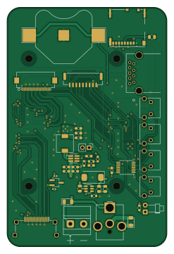
About the Microscope camera PCB
Microscope camera is an open source Raspberry Pi PCB design by Morphdust, published on GitHub. It is a 4-layer board measuring 60 × 90 mm, with 43 components from 34 distinct parts.
Its main chip is the ComputeModule5-CM5, from the Raspberry Pi family. Other key parts include the RT9742SNGV, TPS54202x, 74AHCV17APW and AP22653W6. By type, the board carries 17 capacitors, 7 connectors, 5 resistors, 4 ICs, 4 switches and 3 diodes.
It belongs with the displays & leds designs in this gallery.
From the project
The carrier PCB for CM5 to sit onto and interface to a Pi HQ camera
A carrier PCB for the Raspberry Pi CM5, designed to interface with a Pi HQ camera via CSI for use as a microscope camera.
- Camera: CSI connection to the Raspberry Pi HQ Camera - Display: Waveshare 2.15" four-colour e-ink screen - RTC: Coin cell battery backup for the real-time clock - Connectivity: USB and SD card interfaces - Controls: Four push buttons for: - WPS - Picture taking - Two user-assignable buttons
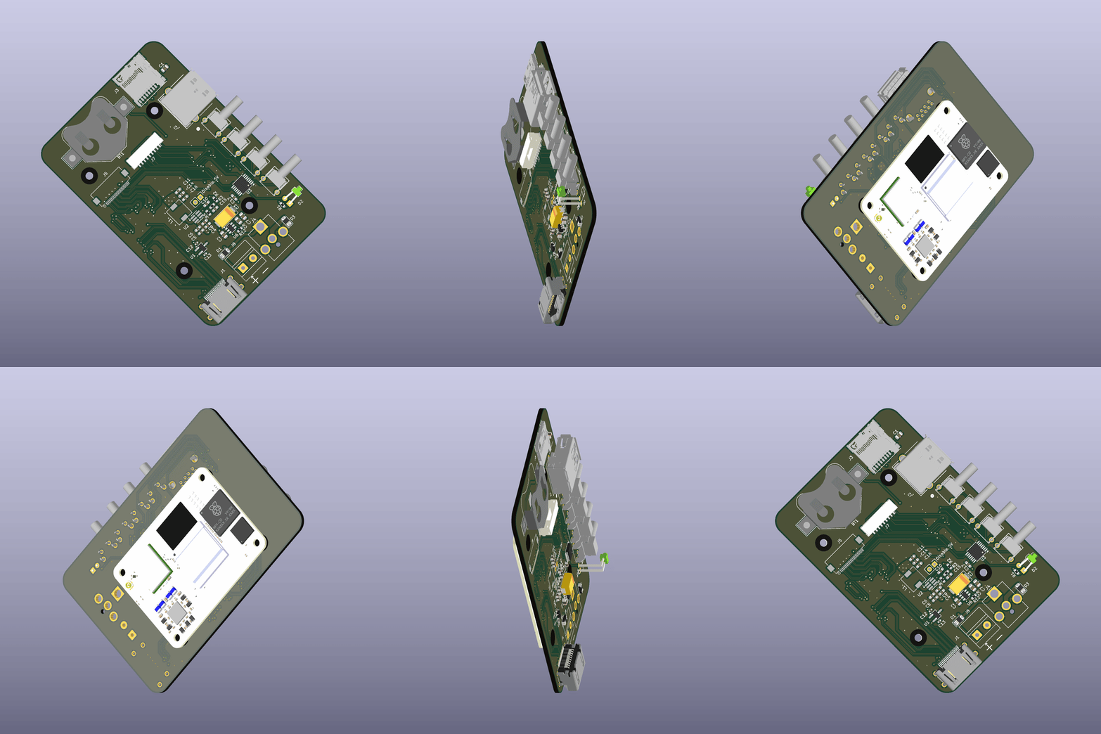
Main components on the Microscope camera
Microscope camera bill of materials (BOM)
43 components, 34 distinct parts.
| Qty | Part | Footprint | Refs |
|---|---|---|---|
| 1 | RT9742SNGV | TSOT-23_HandSoldering | U1 |
| 1 | TPS54202x | DDC0006A-IPC_A | U2 |
| 1 | 74AHCV17APW | TSSOP-14_4.4x5mm_P0.65mm | U3 |
| 1 | AP22653W6 | SOT-23-6 | U6 |
| 1 | HDMI_D_1.4 | HDMI_A_Amphenol_10029449-x01xLF_Horizontal | J1 |
| 1 | USB3_A | CONN_484050003_MOL | J2 |
| 1 | Micro_SD_Card_Det_Hirose_DM3AT | SDCARD_MOLEX_503398-1892 | J3 |
| 1 | Barrel_Jack_MountingPin | BarrelJack_CUI_PJ-063AH_Horizontal_CircularHoles | J4 |
| 1 | Conn_01x22_Female Hirose | Hirose_FH12-22S-0.5SH_1x22-1MP_P0.50mm_Horizontal | J5 |
| 1 | Conn_01x09_Socket | JST_GH_SM09B-GHS-TB_1x09-1MP_P1.25mm_Horizontal | J7 |
| 1 | Screw_Terminal_01x02 | TerminalBlock_MetzConnect_Type011_RT05502HBLC_1x02_P5.00mm_Horizontal | J8 |
| 1 | Battery_Cell | BatteryHolder_Multicomp_BC-2001_1x2032 | BT1 |
| 1 | ComputeModule5-CM5 | Raspberry-Pi-5-Compute-Module | Module1 |
| 1 | Picture Button | SW2_1825027-G_TEC | SW1 |
| 1 | WPS Button | SW2_1825027-G_TEC | SW2 |
| 1 | Misc Button 1 | SW2_1825027-G_TEC | SW3 |
| 1 | Misc Button 0 | SW2_1825027-G_TEC | SW4 |
| 2 | SB120 | D_1206_3216Metric | D1, D3 |
| 1 | LED Green | LED_D1.8mm_W1.8mm_H2.4mm_Horizontal_O3.81mm_Z8.2mm | D2 |
| 1 | 15u | L_6.3x6.3_H3 | L1 |
Show 14 more
| Qty | Part | Footprint | Refs |
|---|---|---|---|
| 4 | 10u | C_0805_2012Metric | C1, C2, C7, C8 |
| 1 | 100uF | CP_EIA-7343-31_Kemet-D | C3 |
| 3 | 10uF | C_0603_1608Metric_Pad1.08x0.95mm_HandSolder | C4, C5, C6 |
| 2 | 100nF | C_0603_1608Metric_Pad1.08x0.95mm_HandSolder | C9, C16 |
| 1 | 0.1uF | C_0603_1608Metric_Pad1.08x0.95mm_HandSolder | C10 |
| 2 | 22u | C_0603_1608Metric_Pad1.08x0.95mm_HandSolder | C11, C14 |
| 2 | 100n | C_0402_1005Metric | C12, C13 |
| 1 | 75pF | C_0603_1608Metric_Pad1.08x0.95mm_HandSolder | C15 |
| 1 | 0.1u | C_0603_1608Metric_Pad1.08x0.95mm_HandSolder | C17 |
| 1 | 1k | R_0603_1608Metric | R1 |
| 1 | 49.9R | R_0603_1608Metric | R2 |
| 1 | 100k | R_0603_1608Metric | R3 |
| 1 | 13.3k | R_0603_1608Metric | R4 |
| 1 | 15k | R_0603_1608Metric | R12 |
Microscope camera design files
The KiCad project lives in the Morphdust/microscope_camera_pcb repository on GitHub; these links point at the commit this page was built from.
Microscope camera: common questions
What microcontroller does the Microscope camera use?
The Microscope camera is built around the ComputeModule5-CM5, from the Raspberry Pi family.
How big is the Microscope camera PCB?
The Microscope camera measures 60 × 90 mm, has 4 copper layers and is 1.6 mm thick.
How many components are on the Microscope camera?
43 components, from 34 distinct parts. The full bill of materials is listed on this page.
Where can I download the Microscope camera design files?
From the Morphdust/microscope_camera_pcb repository on GitHub, which has the KiCad layout and the schematic; the links under Design files point to each one.
Can I use the Microscope camera design in my own project?
The repository has no license, so all rights stay with Morphdust. Use it as a reference, and ask the author before reusing the design.
Can I test firmware for the Microscope camera without the hardware?
Yes. HardLabs builds a simulation of the board from its netlist and BOM, so you can run and debug Raspberry Pi firmware against it before you order a PCB.
More boards in microscope_camera_pcb
Similar boards
 Raspberry Pi
Open source rover
nasa-jpl
220 × 178 mm144 parts2LApache-2.09.7k Raspberry Pi
Iot
dotnet
56 × 65 mm24 parts2LMIT2.4k Raspberry Pi
SPIRIT
SPIRIT-org
82 × 155 mm130 parts6LCERN-OHL-S-2.01.3k Raspberry Pi
CM5RevEng
schlae
55 × 40 mm417 parts10LNo license1.0k Raspberry Pi
Haxo hw
cardonabits
102.4 × 211.3 mm38 parts2LCustom license672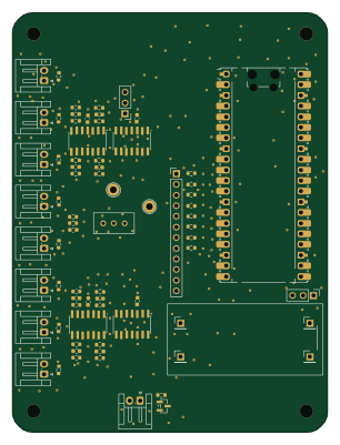 Raspberry Pi
Phased
Neumi
75 × 100 mm71 parts2LNo license507