
Uart cable tester

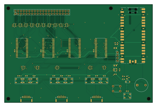
About the Uart cable tester PCB
Uart cable tester is an open source RP2040/RP2350 PCB design by Mykola2, published on GitHub. It is a 2-layer board measuring 135 × 90 mm, with 62 components from 20 distinct parts.
Its main chip is the Pico / WeAct RP2040 (USB-C), from the RP2040/RP2350 family. Other key parts include the MCP23017-E/SO and SN74AHCT1G125DBVR. By type, the board carries 20 resistors, 17 capacitors, 11 diodes, 5 ICs, 5 connectors and 1 module.
It belongs with the displays & leds designs in this gallery.
From the project
design.py is the single source of truth: parts, footprints, pin-to-net map and positions. Everything else is generated from it.
design.py is the single source of truth: parts, footprints, pin-to-net map and positions. Everything else is generated from it.
checkdesign.py checks the exported netlist against firmware/hwmap.py`: - each of the 58 test lines runs connector pin → 220 Ω → the MCP23017 pin the firmware expects - the address straps are correct - no DUT pin touches a power net
The board is routed, so don't run genpcb.py again, because it overwrites the board. After that, make changes in the schematic (or design.py followed by genschematic.py), then use Tools → Update PCB from Schematic (F8).
Main components on the Uart cable tester
Uart cable tester bill of materials (BOM)
62 components, 20 distinct parts — part numbers from the project's BOM.
| Qty | Part | Footprint | Refs |
|---|---|---|---|
| 4 | MCP23017-E/SO | SOIC-28W_7.5x17.9mm_P1.27mm | U1, U2, U3, U4 |
| 1 | SN74AHCT1G125DBVR 74AHCT1G125 | SOT-23-5 | U5 |
| 1 | Raspberry Pi Pico (SC0915) or WeAct Studio RP2040 Pico / WeAct RP2040 (USB-C) | RaspberryPi_Pico_SMD_HandSolder | A1 |
| 1 | MMBT3904 | SOT-23 | Q1 |
| 1 | 2x20 2.54mm male pin header RPi 40-pin (DUT) | PinHeader_2x20_P2.54mm_Vertical | J1 |
| 1 | JST SM06B-GHS-TB(LF)(SN) TELEM1 (DUT) | JST_GH_SM06B-GHS-TB_1x06-1MP_P1.25mm_Horizontal | J2 |
| 1 | JST SM06B-GHS-TB(LF)(SN) TELEM2 (DUT) | JST_GH_SM06B-GHS-TB_1x06-1MP_P1.25mm_Horizontal | J3 |
| 1 | JST SM06B-GHS-TB(LF)(SN) TELEM3 (DUT) | JST_GH_SM06B-GHS-TB_1x06-1MP_P1.25mm_Horizontal | J4 |
| 1 | 1x4 2.54mm header (DNP) OLED (opt.) | PinHeader_1x04_P2.54mm_Vertical | J5 |
| 1 | TMB12A05 (12mm 5V active, 7.6mm pitch) 5V active buzzer | Buzzer_12x9.5RM7.6 | BZ1 |
| 1 | 6x6mm THT tactile switch START / LEARN | SW_PUSH_6mm_H5mm | SW1 |
| 10 | WS2812B-5050 WS2812B | LED_WS2812B_PLCC4_5.0x5.0mm_P3.2mm | D1, D2, D3, D4, D5, D6, D7, D8 +2 |
| 1 | 1N4148W | D_SOD-123 | D11 |
| 15 | 0603 100nF X7R 16V 100n | C_0603_1608Metric | C1, C2, C3, C4, C5, C8, C9, C10 +7 |
| 2 | 0805 10uF X5R 16V 10u | C_0805_2012Metric | C6, C7 |
| 1 | 0603 330R 330 | R_0603_1608Metric | R1 |
| 2 | 0603 4.7k 4k7 | R_0603_1608Metric | R2, R3 |
| 1 | 0603 1k 1k | R_0603_1608Metric | R4 |
| 1 | 0603 10k 10k | R_0603_1608Metric | R5 |
| 15 | YC164-JR-07220RL (4x220R 0603 convex) 4x220 | R_Array_Convex_4x0603 | RN1, RN2, RN3, RN4, RN5, RN6, RN7, RN8 +7 |
Uart cable tester design files
The KiCad project lives in the Mykola2/uart-cable-tester repository on GitHub; these links point at the commit this page was built from.
Uart cable tester: common questions
What microcontroller does the Uart cable tester use?
The Uart cable tester is built around the Pico / WeAct RP2040 (USB-C), from the RP2040/RP2350 family.
How big is the Uart cable tester PCB?
The Uart cable tester measures 135 × 90 mm, has 2 copper layers and is 1.6 mm thick.
How many components are on the Uart cable tester?
62 components, from 20 distinct parts, with part numbers taken from the project's own BOM. The full bill of materials is listed on this page.
Where can I download the Uart cable tester design files?
From the Mykola2/uart-cable-tester repository on GitHub, which has the KiCad layout, the schematic and the BOM; the links under Design files point to each one.
Can I use the Uart cable tester design in my own project?
The repository has no license, so all rights stay with Mykola2. Use it as a reference, and ask the author before reusing the design.
Can I test firmware for the Uart cable tester without the hardware?
Yes. HardLabs builds a simulation of the board from its netlist and BOM, so you can run and debug RP2040/RP2350 firmware against it before you order a PCB.
Similar boards
 RP2040/RP2350
Open Book Abridged Edition
joeycastillo
85 × 115 mm29 parts2LCC-BY-SA-4.08.1k RP2040/RP2350
Corne
foostan
277.2 × 107.5 mm164 parts2LCC-BY-4.07.7k RP2040/RP2350
Corne
277.2 × 107.5 mm164 parts2LCC-BY-4.07.7k RP2040/RP2350
Jitx design
gusmanb
55.5 × 65 mm26 parts4LGPL-3.05.0k RP2040/RP2350
LogicAnalyzer
57 × 55.2 mm6 parts2LGPL-3.05.0k RP2040/RP2350
Main
google
98 × 71 mm102 parts2LApache-2.02.9k