
IoT AIO

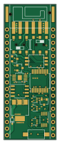
About the IoT AIO PCB
IoT AIO is an open source RP2040/RP2350 PCB design by N5GEH, published on GitHub under the MIT license. It is a 4-layer board measuring 20 × 52 mm, with 58 components from 41 distinct parts.
Its main chip is the ESP-32-PICO-KIT-V4, from the RP2040/RP2350 family. Other key parts include the TLV07IDR, XTR111AIDGQR, TLV333IDCKR, LM4040DCK-2.0 and MAX31865. By type, the board carries 25 resistors, 15 capacitors, 9 ICs, 4 switches, 3 transistors and 1 connector.
It belongs with the iot & wireless designs in this gallery.
From the project
IoT-AIO is a wireless adapter for developing IoT applications for Industrial and Building Automation Systems based on the Espressif chipset ESP32. The adapter is compatible with: - current loop signals (0/4-20 mA) - voltage signals (0/2-10 V) - passive sensors (RTD, Strain Gauge,
IoT-AIO is a wireless adapter for developing IoT applications for Industrial and Building Automation Systems based on the Espressif chipset ESP32. The adapter is compatible with: - current loop signals (0/4-20 mA) - voltage signals (0/2-10 V) - passive sensors (RTD, Strain Gauge,..)
The library allows the implemention of IoT applications that rely on MQTT protocol via WiFi/NB-IoT/LTE Cat-M1 interfaces.
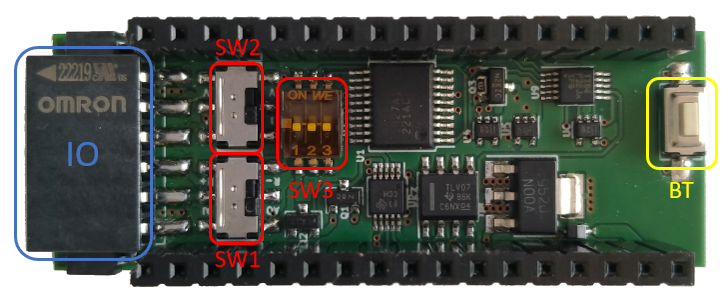
Main components on the IoT AIO
IoT AIO bill of materials (BOM)
58 components, 41 distinct parts.
| Qty | Part | Footprint | Refs |
|---|---|---|---|
| 1 | ESP-32-PICO-KIT-V4 | ESP32v4 | U1 |
| 1 | TLV07IDR | SOIC-8_3.9x4.9mm_P1.27mm | U2 |
| 1 | XTR111AIDGQR | MSOP-10_3x3mm_P0.5mm_ThermalPAD | U3 |
| 2 | TLV333IDCKR | SOT-353_SC-70-5 | U4, U6 |
| 1 | LM4040DCK-2.0 | SOT-353_SC-70-5 | U5 |
| 1 | MAX31865 | SSOP-20_5.3x7.2mm_P0.65mm | U7 |
| 1 | LM340MP-5.0/NOPB | SOT-223-3_TabPin2 | U8 |
| 1 | TMUX1204 | VSSOP-10_3x3mm_P0.5mm | U9 |
| 1 | MMBT5087LT3G | SOT-23 | Q1 |
| 1 | ISS55EP06LMXTSA1 | SOT-23 | Q2 |
| 1 | SI2302 | SOT-23 | Q3 |
| 1 | Conn_01x06 | XW4L-06A1-H1 | J1 |
| 1 | SW_3PST | 416131160803 | SW1 |
| 1 | SW_SPDT_x2 | AYZ0202AGRL | SW2 |
| 1 | SW_Push | PTS636 | SW3 |
| 1 | SW_DPDT_x2 | AYZ0202AGRL | SW4 |
| 1 | D_Schottky | BAT60A | D1 |
| 3 | 1u | C_0603_1608Metric | C1, C3, C6 |
| 8 | 100n | C_0603_1608Metric | C2, C4, C5, C8, C9, C10, C12, C13 |
| 1 | 10n | C_0603_1608Metric | C7 |
Show 21 more
| Qty | Part | Footprint | Refs |
|---|---|---|---|
| 1 | 220n | C_0603_1608Metric | C11 |
| 1 | 100n | R_0603_1608Metric | C14 |
| 1 | 2u | C_0603_1608Metric | C15 |
| 3 | 10k | R_0603_1608Metric | R1, R11, R24 |
| 1 | 4.64k 0.1% | R_0603_1608Metric | R2 |
| 1 | 10k 0.1% | R_0603_1608Metric | R3 |
| 1 | 22k | R_0603_1608Metric | R4 |
| 1 | 8.2k | R_0603_1608Metric | R5 |
| 2 | 33k 0.1% | R_0603_1608Metric | R6, R21 |
| 2 | 3.32k 0.1% | R_0603_1608Metric | R7, R19 |
| 1 | 4990 0.1% | R_0603_1608Metric | R8 |
| 2 | 15 | R_0603_1608Metric | R9, R10 |
| 2 | 3.3k | R_0603_1608Metric | R12, R23 |
| 1 | 33k | R_0603_1608Metric | R13 |
| 2 | 1k | R_0603_1608Metric | R14, R22 |
| 1 | 619 | R_0603_1608Metric | R15 |
| 1 | 1k 0.1% | R_0603_1608Metric | R16 |
| 1 | 2.2k 0.1% | R_0603_1608Metric | R17 |
| 1 | 470 | R_0603_1608Metric | R18 |
| 1 | 45.3 0.1% | R_0603_1608Metric | R20 |
| 1 | 402 0.1% | R_0603_1608Metric | R29 |
IoT AIO design files
The KiCad project lives in the N5GEH/n5geh.devices.iot_wa_aio repository on GitHub; these links point at the commit this page was built from.
IoT AIO: common questions
What microcontroller does the IoT AIO use?
The IoT AIO is built around the ESP-32-PICO-KIT-V4, from the RP2040/RP2350 family.
How big is the IoT AIO PCB?
The IoT AIO measures 20 × 52 mm, has 4 copper layers and is 1.6 mm thick.
How many components are on the IoT AIO?
58 components, from 41 distinct parts. The full bill of materials is listed on this page.
Where can I download the IoT AIO design files?
From the N5GEH/n5geh.devices.iot_wa_aio repository on GitHub, which has the KiCad layout; the links under Design files point to each one.
Can I use the IoT AIO design in my own project?
Yes, under the terms of its MIT license, which N5GEH chose for the repository.
Can I test firmware for the IoT AIO without the hardware?
Yes. HardLabs builds a simulation of the board from its netlist and BOM, so you can run and debug RP2040/RP2350 firmware against it before you order a PCB.
More boards in n5geh.devices.iot_wa_aio
Similar boards
 RP2040/RP2350
Open Book Abridged Edition
joeycastillo
85 × 115 mm29 parts2LCC-BY-SA-4.08.1k RP2040/RP2350
Corne
foostan
277.2 × 107.5 mm164 parts2LCC-BY-4.07.7k RP2040/RP2350
Corne
277.2 × 107.5 mm164 parts2LCC-BY-4.07.7k RP2040/RP2350
Jitx design
gusmanb
55.5 × 65 mm26 parts4LGPL-3.05.0k RP2040/RP2350
LogicAnalyzer
57 × 55.2 mm6 parts2LGPL-3.05.0k RP2040/RP2350
Main
google
98 × 71 mm102 parts2LApache-2.02.9k