
ODR-1 RF Amp & Antenna Tuner Board

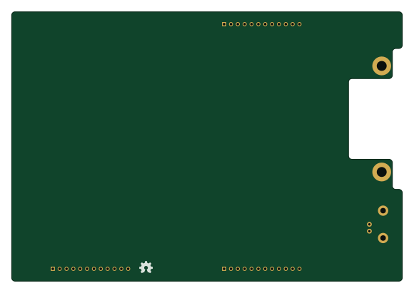
About the ODR-1 RF Amp & Antenna Tuner Board
ODR-1 RF Amp & Antenna Tuner Board is an open source PCB design by N7IFC, published on GitHub. It is a 2-layer board measuring 144.8 × 100 mm, with 8 components from 5 distinct parts.
By type, the board carries 4 connectors, 1 capacitor and 1 resistor.
It belongs with the rf & radio designs in this gallery.
From the project
Hardware files for ODR-1 Radio
ODR-1 RF Amp & Antenna Tuner Board bill of materials (BOM)
8 components, 5 distinct parts — part numbers from the project's BOM.
| Qty | Part | Footprint | Refs |
|---|---|---|---|
| 1 | CON_BNC | CON_BNC-1 | J17 |
| 3 | CONN_12 | SIL-12-1 | P2, P4, P6 |
| 2 | CONN_1 | MH-6-32 | MH1, MH2 |
| 1 | CL21B103KC65PNC C | SM0805 | C1 |
| 1 | ERJ-6ENF22R1V R | SM0805 | R1 |
ODR-1 RF Amp & Antenna Tuner Board design files
The KiCad project lives in the N7IFC/ODR-1_Hardware repository on GitHub; these links point at the commit this page was built from.
ODR-1 RF Amp & Antenna Tuner Board: common questions
How big is the ODR-1 RF Amp & Antenna Tuner Board?
The ODR-1 RF Amp & Antenna Tuner Board measures 144.8 × 100 mm, has 2 copper layers and is 1.6 mm thick.
How many components are on the ODR-1 RF Amp & Antenna Tuner Board?
8 components, from 5 distinct parts, with part numbers taken from the project's own BOM. The full bill of materials is listed on this page.
Where can I download the ODR-1 RF Amp & Antenna Tuner Board design files?
From the N7IFC/ODR-1_Hardware repository on GitHub, which has the KiCad layout and the BOM; the links under Design files point to each one.
Can I use the ODR-1 RF Amp & Antenna Tuner Board design in my own project?
The repository has no license, so all rights stay with N7IFC. Use it as a reference, and ask the author before reusing the design.
More boards in ODR-1_Hardware
Similar boards
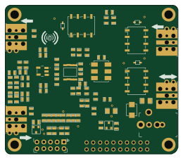
Hat
pa3gsb
65 × 56 mm81 parts2LNo license675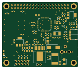
Radioberry juice
65 × 56 mm87 parts2LNo license675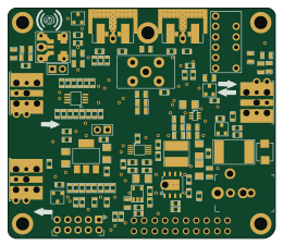
Radioberry preamp
65 × 56 mm137 parts2LNo license675
Goodwatch20
travisgoodspeed
25.6 × 27.6 mm20 parts2LNo license568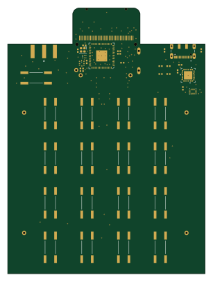
GoodPocketWatch
75.2 × 101.2 mm56 parts2LNo license568
Goodwatch31
25.6 × 27.6 mm23 parts2LNo license568