
41 open source boards using the PCA9685
Real designs built with the PCA9685, from public GitHub projects: a quick way to see how others power, decouple and connect it. Each board comes with its KiCad files, full parts list and a render — and you can simulate its firmware on HardLabs.
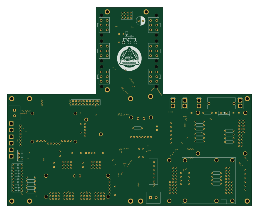 Raspberry Pi
Open source rover
nasa-jpl
220 × 178 mm144 parts2LApache-2.09.7k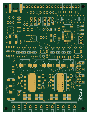 AVR/Arduino
ATMEGA328-Motor-Board
AntonioMR
77 × 100 mm171 parts2LNo license39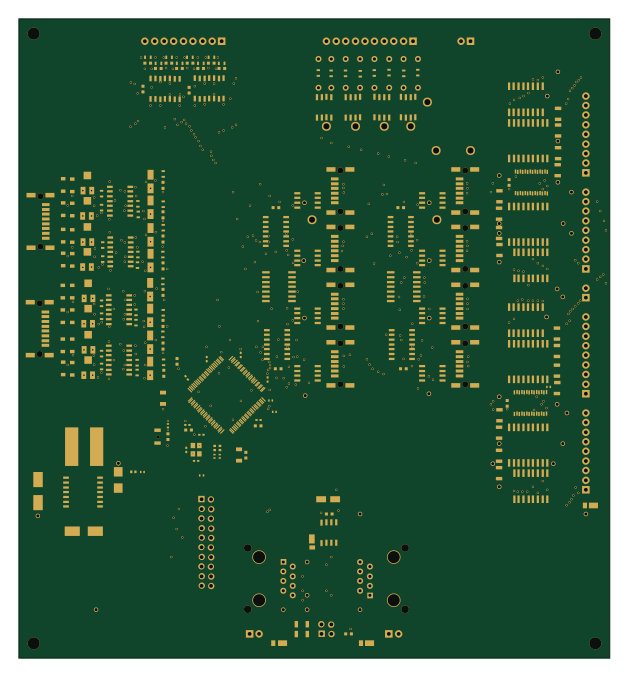 NXP
LPC176x MultiFunction
RobertPHeller
156.2 × 168.9 mm223 parts2LCC-BY-4.024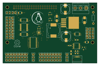
96boards robomezzi
mwelling
85 × 54 mm112 parts4LCC-BY-SA-4.06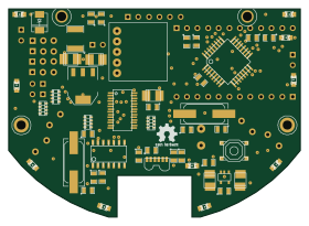 AVR/Arduino
Cosmoneer-Proto
cosmospioneering
70 × 50 mm71 parts4LNo license5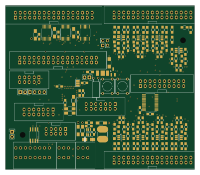 ESP32
SensactHs
klaus-liebler
100 × 86.5 mm317 parts2LApache-2.04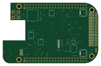
RoboCape
PREDICT-EPFL
86.4 × 54.6 mm113 partsNo license4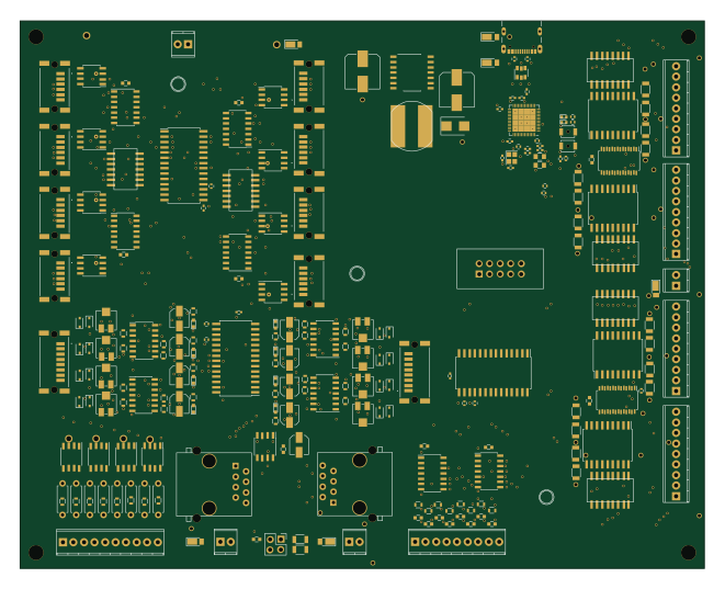 ESP32
ESP32-S3-MegaMultiFunction
165.1 × 132.1 mm238 parts2LCC-BY-4.03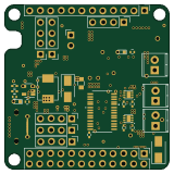
NeoBoard
alvaroferran
40 × 40 mm73 parts2LNo license3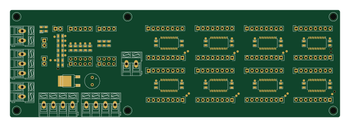
Driver unit
davidanton
172.5 × 56.1 mm66 parts2LGPL-3.03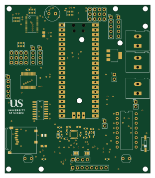 RP2040/RP2350
OpenEduBot
shepai
77.1 × 89.2 mm40 parts2LNo license3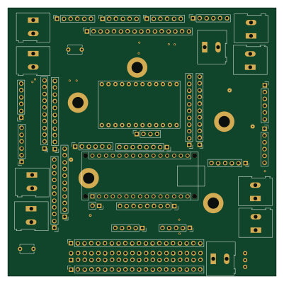 AVR/Arduino
Mercury 2021
ksurct
100 × 100 mm40 parts2LApache-2.02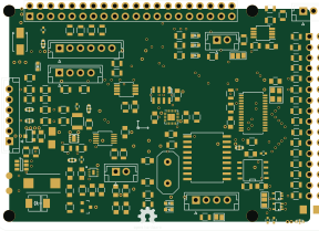 Raspberry Pi
DronPi
radioelf
71.8 × 50.9 mm135 parts2LNo license1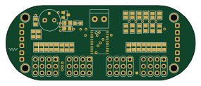
SirGrab
Will946
71.1 × 28 mm44 parts2LMIT1- schematic only · 27 partsESP32
Flathead robot
michaelsumin78-hue
27 partsNo license1 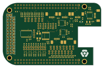
Cvra cape
cvra
86.4 × 54.6 mm160 parts2LNo license0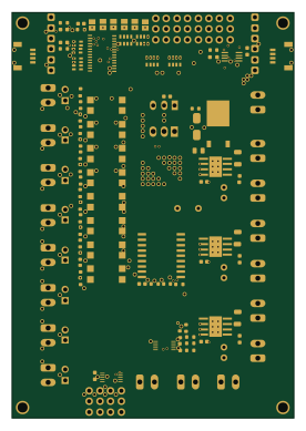 ESP32
Rev0
Hasatio
67.3 × 96.9 mm125 parts2LNo license0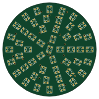 NXP
Kanelbulle
h4xxel
50 × 50 mm86 parts2LMIT0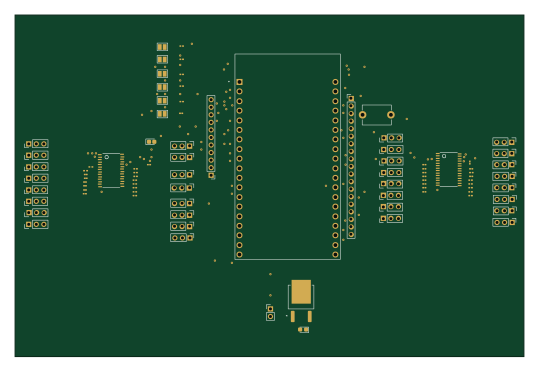 ESP32
Navrh03
Ejdmmm
134.6 × 90.4 mm82 parts2LNo license0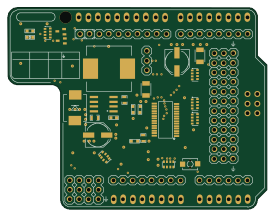 AVR/Arduino
ServoShield
freetronics
68.6 × 53.3 mm56 parts2LNo license0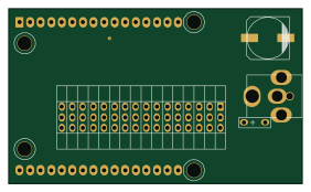
Servo controller 3x2
janelia-kicad
70.5 × 41.9 mm15 parts2LCustom license0- schematic only · 42 partsAVR/Arduino
Saxion-Sky-Projector
Emanuel-de-Jong
42 partsNo license0 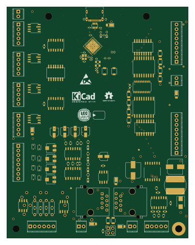 ESP32
ESP32-S3-MultiFunction
99.1 × 125.7 mm141 parts2LCC-BY-4.03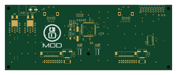 NXP
Top board
mod-audio
170 × 66.6 mm125 parts2LNo license1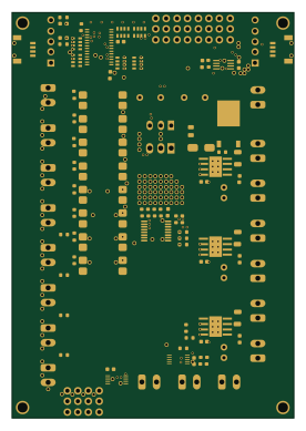 ESP32
Rev1
67.3 × 96.9 mm108 parts2LNo license0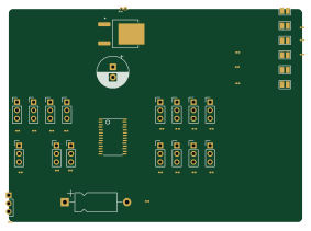
MyPCB 01
70.7 × 51.5 mm50 parts2LNo license0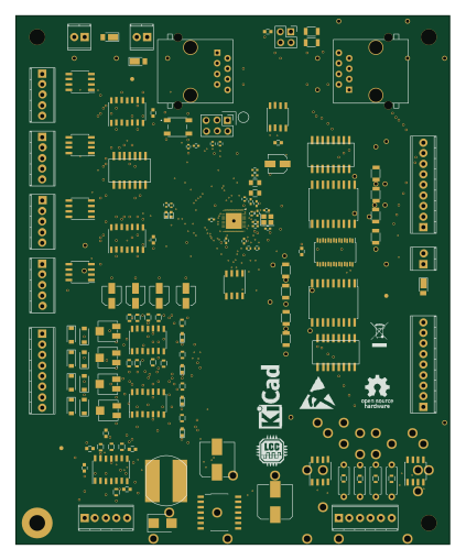 ESP32
ESP32-D0WD-V3-MultiFunction
104.1 × 127 mm137 parts2LCC-BY-4.03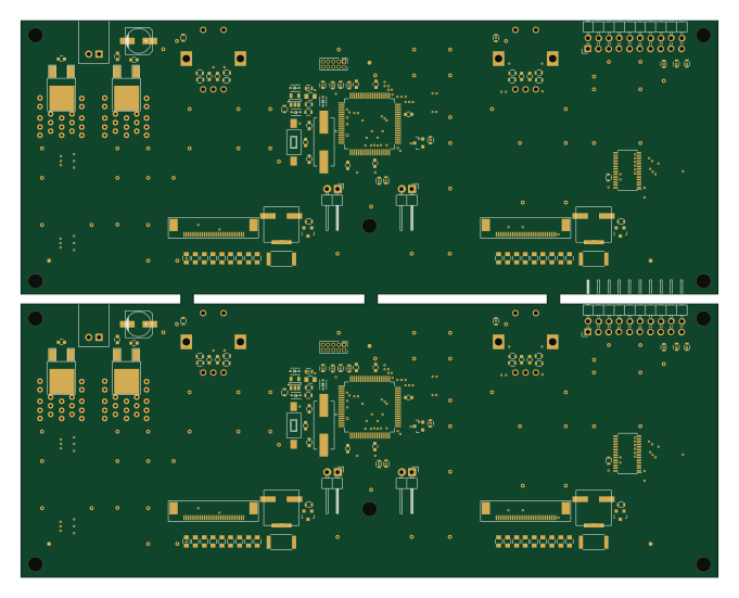 NXP
Top board panel
170 × 135.7 mm125 parts2LNo license1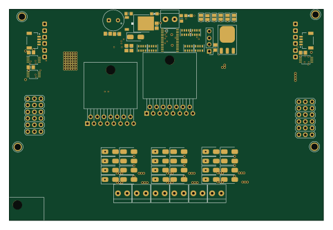 ESP32
PCA9685+L298
120.4 × 81.1 mm92 parts2LNo license0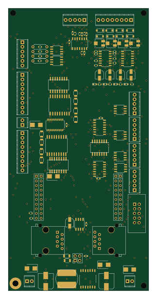
TivaMultiFunctionBoard
76.2 × 153.7 mm114 parts2LCC-BY-4.024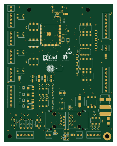 ESP32
ESP32-S3-MultiFunction wroom
99.1 × 125.7 mm127 parts2LCC-BY-4.03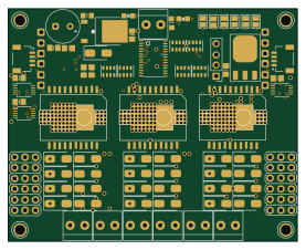 ESP32
SMD
69.2 × 55.6 mm92 parts2LNo license0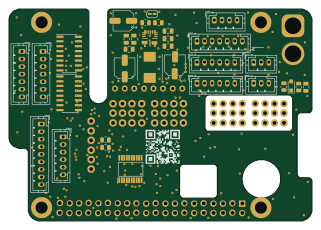 Raspberry Pi
Prime Mover
dannyandreev
80.1 × 56 mm37 parts2LMIT0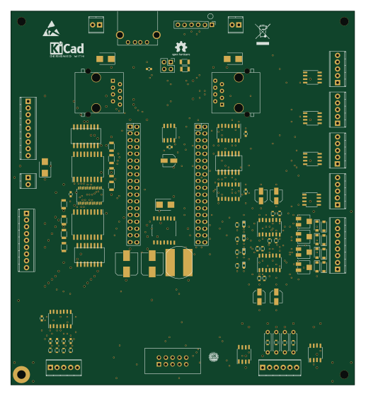
PocketBeagleMultifuntion
128.3 × 139.7 mm111 parts2LCC-BY-4.024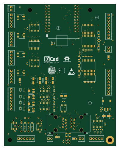 ESP32
ESP32-T7S3-MultiFunction
99.1 × 125.7 mm116 parts2LCC-BY-4.03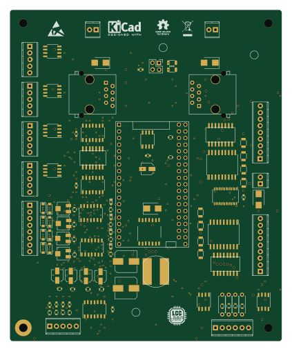 ESP32
ESP32-MultiFunction
104.1 × 127 mm109 parts2LCC-BY-4.03
How designs wire the PCA9685
Read from the KiCad layouts of 23 open source designs, one per repository: what each pin of the PCA9685 connects to, and the resistors, capacitors and other passives placed on it.
- The SCL pin has a pull-up to 3.3V on 15 of 21 designs, most often 4.7 kΩ (then 10 kΩ).
- The SDA pin has a pull-up to 3.3V on 15 of 21 designs, most often 4.7 kΩ (then 10 kΩ).
- The EXTCLK pin is tied to GND on 16 of 21 designs (not connected on 3, a signal on 2).
- The A5 pin is tied to GND on 14 of 21 designs (a signal on 5).
| Pin | Connected to | Parts on the pin |
|---|---|---|
| PWM0pin 6 | Connected to: Signal 83% |
|
| PWM1pin 7 | Connected to: Signal 86% |
|
| PWM2pin 8 | Connected to: Signal 86% |
|
| PWM3pin 9 | Connected to: Signal 91% |
|
| PWM4pin 10 | Connected to: Signal 86% |
|
| PWM5pin 11 | Connected to: Signal 77% |
|
| PWM6pin 12 | Connected to: Signal 86% |
|
| PWM7pin 13 | Connected to: Signal 77% · not connected 23% |
|
| GNDpin 14 | Connected to: GND 63% · not connected 22% | — |
| PWM8pin 15 | Connected to: Signal 81% · not connected 19% |
|
| PWM9pin 16 | Connected to: Signal 76% · not connected 24% |
|
| PWM10pin 17 | Connected to: Signal 76% · not connected 24% |
|
| PWM11pin 18 | Connected to: Signal 76% · not connected 24% |
|
| PWM12pin 19 | Connected to: Signal 81% · not connected 19% |
|
| PWM13pin 20 | Connected to: Signal 81% · not connected 19% |
|
| PWM14pin 21 | Connected to: Signal 86% |
|
| PWM15pin 22 | Connected to: Signal 67% · not connected 33% |
|
| #OEpin 23 | Connected to: Signal 71% · GND 19% |
|
| A5pin 24 | Connected to: GND 67% · a signal 24% | — |
| EXTCLKpin 25 | Connected to: GND 76% | — |
| SCLpin 26 | Connected to: The microcontroller 29%, a connector 29% |
|
| SDApin 27 | Connected to: A connector 33%, the microcontroller 29% |
|
| VDDpin 28 | Connected to: 5V 81% |
|
5 more pins vary from design to design. Connections count pins, parts count designs; values in brackets are how many parts had that value. Designs read include Open source rover by nasa-jpl, ATMEGA328-Motor-Board by AntonioMR, LPC176x MultiFunction by RobertPHeller and 96boards robomezzi by mwelling.
The PCA9685 in open source designs
The gallery holds 41 open source boards using the PCA9685 from 26 GitHub repositories; a typical one measures about 86.4 × 86.5 mm and carries around 102 components.
89% are two-layer designs, the rest use four layers or more, and 46% carry an open source license.
The most starred is Open source rover by nasa-jpl.
Parts used alongside the PCA9685
Microcontrollers on boards using the PCA9685
What boards using the PCA9685 are built for
PCA9685: common questions
Where can I find a PCA9685 reference design?
Each of the 41 boards on this page is a real design using the PCA9685. Open one to see how it is wired up, with the full BOM, a render of the layout and links to its KiCad files.
What pull-up resistor is used on the PCA9685 SCL pin?
The SCL pin has a pull-up to 3.3V on 15 of 21 designs, most often 4.7 kΩ (then 10 kΩ). Counted from the KiCad layouts of 23 open source designs using the PCA9685.
What pull-up resistor is used on the PCA9685 SDA pin?
The SDA pin has a pull-up to 3.3V on 15 of 21 designs, most often 4.7 kΩ (then 10 kΩ). Counted from the KiCad layouts of 23 open source designs using the PCA9685.
How is the PCA9685 EXTCLK pin connected?
The EXTCLK pin is tied to GND on 16 of 21 designs (not connected on 3, a signal on 2). Counted from the KiCad layouts of 23 open source designs using the PCA9685.
What parts are used alongside the PCA9685?
The MPU-9250, 74HCT00, 74HCT14, BEAGLEBONE and BQ32000 appear in the most repositories here.
Which microcontrollers do boards using the PCA9685 use?
Most are built on ESP32 (16), AVR/Arduino (5), NXP (4) and Raspberry Pi (3).
How big is a typical board using the PCA9685?
The median is 86.4 × 86.5 mm, and 89% are two-layer designs.
What is the most popular open source board using the PCA9685?
By GitHub stars, Open source rover by nasa-jpl, with 9,675 stars.
Can I simulate one of these boards using the PCA9685 before building it?
Yes. HardLabs turns a board's netlist and BOM into a working simulation, so you can boot and test firmware against it with no hardware on your desk.