
JTAG-SWD-adapter

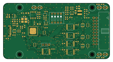
About the JTAG-SWD-adapter PCB
JTAG-SWD-adapter is an open source PCB design by Neofoxx, published on GitHub. It is a 2-layer board measuring 91.3 × 48.3 mm, with 98 components from 38 distinct parts.
Other key parts include the SRV05-4, LN1134A332MR-G, 93LCxxB, FT2232H-56Q and BL8028. By type, the board carries 42 resistors, 25 capacitors, 13 ICs, 6 diodes, 4 inductors and 3 transistors.
It belongs with the usb & debug tools designs in this gallery.
From the project
Universal JTAG/SWD/UART adapter based on FT2232H
- USB Type-C connector - 1.8V - 5V traget supply - JTAG and SWD support on channel A, UART support on channel B. - ESD protection of USB and of target - Integrated power section, to power target from the adapter (5V/3.3V/2.5V/1.8V available) - Similar pinout to the standard found on commercial JTAG/SWD adapters, with the addition of UART pins - JTAG/SWD programming with simultaneous UART communication - LEDs for USB power, Target power, SWD interface, Activity, and RX&TX of the UART
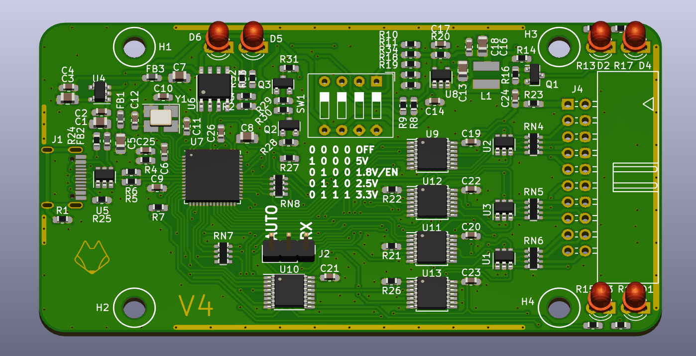
Main components on the JTAG-SWD-adapter
JTAG-SWD-adapter bill of materials (BOM)
98 components, 38 distinct parts — part numbers from the project's BOM.
| Qty | Part | Footprint | Refs |
|---|---|---|---|
| 4 | SRV05-4 | SOT-23-6 | U1, U2, U3, U5 |
| 1 | LN1134A332MR-G | SOT-23-5 | U4 |
| 1 | 93LCxxB | SOIC-8_3.9x4.9mm_P1.27mm | U6 |
| 1 | FT2232H-56Q | QFN-56-1EP_8x8mm_P0.5mm_EP5.6x5.6mm | U7 |
| 1 | BL8028 | SOT-23-5 | U8 |
| 4 | 74LVC125 | TSSOP-14_4.4x5mm_P0.65mm | U9, U11, U12, U13 |
| 1 | 74LVC157A | TSSOP-16_4.4x5mm_P0.65mm | U10 |
| 2 | BC847 | SOT-23 | Q1, Q2 |
| 1 | BC857 | SOT-23 | Q3 |
| 1 | 12MHz | Crystal_SMD_3225-4Pin_3.2x2.5mm_HandSoldering | Y1 |
| 1 | USB_C_Receptacle_USB2.0 | Jing USB C 2.0 16pin receptable | J1 |
| 1 | Conn_01x03_Male | PinHeader_1x03_P2.54mm_Vertical | J2 |
| 1 | CONN_02X10 | Multicomp_MC9A22-2034_2x10_P2.54mm_Horizontal | J4 |
| 1 | SW_DIP_x04 | SW_DIP_SPSTx04_Slide_9.78x12.34mm_W7.62mm_P2.54mm | SW1 |
| 6 | LED | LED_D3.0mm | D1, D2, D3, D4, D5, D6 |
| 2 | 600R, 1A | L_0603_1608Metric_Pad1.05x0.95mm_HandSolder | FB1, FB3 |
| 1 | 220R, 2.5A | L_0603_1608Metric_Pad1.05x0.95mm_HandSolder | FB2 |
| 1 | 1.5uH | SMNR4018_(1616FPS) | L1 |
| 5 | 4u7 | C_0805_2012Metric_Pad1.15x1.40mm_HandSolder | C1, C3, C5, C7, C8 |
| 14 | 100nF | C_0603_1608Metric_Pad1.05x0.95mm_HandSolder | C2, C4, C6, C9, C11, C14, C18, C19 +6 |
Show 18 more
| Qty | Part | Footprint | Refs |
|---|---|---|---|
| 2 | 27pF | C_0603_1608Metric_Pad1.05x0.95mm_HandSolder | C10, C12 |
| 2 | 4.7uF | C_0805_2012Metric_Pad1.15x1.40mm_HandSolder | C13, C16 |
| 2 | DNS | C_0603_1608Metric_Pad1.05x0.95mm_HandSolder | C17, C25 |
| 1 | 0R | R_0603_1608Metric_Pad1.05x0.95mm_HandSolder | R1 |
| 4 | 10k | R_0603_1608Metric_Pad1.05x0.95mm_HandSolder | R2, R7, R27, R30 |
| 1 | 2k | R_0603_1608Metric_Pad1.05x0.95mm_HandSolder | R3 |
| 1 | 12k | R_0603_1608Metric_Pad1.05x0.95mm_HandSolder | R4 |
| 2 | 10R | R_0603_1608Metric_Pad1.05x0.95mm_HandSolder | R5, R6 |
| 5 | 100k | R_0603_1608Metric_Pad1.05x0.95mm_HandSolder | R8, R14, R16, R28, R29 |
| 11 | 1k | R_0603_1608Metric_Pad1.05x0.95mm_HandSolder | R9, R12, R13, R15, R17, R21, R22, R26 +3 |
| 1 | 180k | R_0603_1608Metric_Pad1.05x0.95mm_HandSolder | R10 |
| 1 | 470k | R_0603_1608Metric_Pad1.05x0.95mm_HandSolder | R11 |
| 3 | 220k | R_0603_1608Metric_Pad1.05x0.95mm_HandSolder | R18, R19, R20 |
| 1 | 1R | R_0603_1608Metric_Pad1.05x0.95mm_HandSolder | R23 |
| 2 | 5k1 | R_0603_1608Metric_Pad1.05x0.95mm_HandSolder | R24, R25 |
| 1 | 330k | R_0603_1608Metric_Pad1.05x0.95mm_HandSolder | R34 |
| 3 | 4x470k | R_Array_Convex_4x0603 | RN1, RN2, RN3 |
| 5 | 4x220R | R_Array_Convex_4x0603 | RN4, RN5, RN6, RN7, RN8 |
JTAG-SWD-adapter design files
The KiCad project lives in the Neofoxx/JTAG-SWD-adapter repository on GitHub; these links point at the commit this page was built from.
JTAG-SWD-adapter: common questions
How big is the JTAG-SWD-adapter PCB?
The JTAG-SWD-adapter measures 91.3 × 48.3 mm, has 2 copper layers and is 1.6 mm thick.
How many components are on the JTAG-SWD-adapter?
98 components, from 38 distinct parts, with part numbers taken from the project's own BOM. The full bill of materials is listed on this page.
Where can I download the JTAG-SWD-adapter design files?
From the Neofoxx/JTAG-SWD-adapter repository on GitHub, which has the KiCad layout and the BOM; the links under Design files point to each one.
Can I use the JTAG-SWD-adapter design in my own project?
The repository has no license, so all rights stay with Neofoxx. Use it as a reference, and ask the author before reusing the design.
Similar boards
USB Hub Test
osy
50 × 50 mm85 parts4LCC-BY-4.0703
XG Station Power
54.3 × 91 mm9 parts2LCC-BY-4.0703
FW-EC-DongleHiderPlus
LeoDJ
28.2 × 26.1 mm14 parts4LCERN-OHL-W-2.0490
Adapter tsop48
bbogush
48 × 33 mm3 parts2LGPL-3.0389
Adapter tsop48 solder
48 × 33 mm3 parts2LGPL-3.0389
Adapter soic8 solder
48 × 20 mm3 parts2LGPL-3.0389