
Tmc2209 devboard

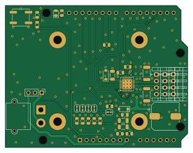
About the Tmc2209 devboard PCB
Tmc2209 devboard is an open source PCB design by Neumi, published on GitHub. It is a 2-layer board measuring 69 × 53.8 mm, with 35 components from 22 distinct parts.
Other key parts include the TMC2209-LA. By type, the board carries 12 resistors, 8 capacitors, 5 connectors, 5 jumpers, 3 diodes and 1 IC.
It belongs with the robotics & motion and dev boards & breakouts designs in this gallery.
From the project
An Arduino shield to test the TMC2209 stepper motion controller by Trinamic.
This board should cover all options and IOs that Trinamic provides for its TMC2209.
Facts: - All TMC2209 pins are connected to digital pins of the Arduino. - XT30 power connector - voltage source selector Arduino VIN or XT30 - TVS diodes on 5v and 28V lane of the TMC2209 - different wiring schemes for the JST motor connector (because getting the right phases is not easy apparently!) - different current setting selectable with solder bridges (or custom resistor also possible) - motor voltage sensing via voltage divider on A0 - reset button for Arudino + power LED

Main components on the Tmc2209 devboard
Tmc2209 devboard bill of materials (BOM)
35 components, 22 distinct parts.
| Qty | Part | Footprint | Refs |
|---|---|---|---|
| 1 | TMC2209-LA | QFN50P500X500X90-29N | U1 |
| 1 | Conn_01x02_Male | AMASS_XT30PW-M_1x02_P2.50mm_Horizontal | J1 |
| 1 | Conn_01x03_Pin | PinHeader_1x03_P2.54mm_Vertical | J2 |
| 3 | motor_conn | JST_EH_S4B-EH_1x04_P2.50mm_Horizontal | J4, J5, J6 |
| 4 | Jumper | SolderJumper-2_P1.3mm_Open_RoundedPad1.0x1.5mm | JP1, JP2, JP3, JP4 |
| 1 | SolderJumper_2_Bridged | SolderJumper-2_P1.3mm_Bridged_RoundedPad1.0x1.5mm | JP5 |
| 1 | SW_Push | SW_Push_1P1T_NO_CK_KSC6xxJ | SW1 |
| 1 | D_TVS_30V | D_SOD-123 | D1 |
| 1 | LED | LED_0805_2012Metric | D2 |
| 1 | D_TVS_5V | D_SOD-123 | D3 |
| 3 | C100nF | C_0805_2012Metric | C1, C5, C7 |
| 1 | C10uF | C_1206_3216Metric | C2 |
| 1 | C4.7uF | C_1206_3216Metric | C3 |
| 1 | C_330uF | CP_Elec_10x10 | C4 |
| 1 | C22nF 50V | C_0805_2012Metric | C6 |
| 1 | C2.2-4.7uF ceramic | C_1206_3216Metric | C8 |
| 2 | R10k | R_0805_2012Metric | R1, R3 |
| 1 | R2k | R_0805_2012Metric | R2 |
| 1 | R330 | R_0805_2012Metric | R4 |
| 5 | R33k | R_0805_2012Metric | R5, R6, R7, R8, R9 |
Show 2 more
| Qty | Part | Footprint | Refs |
|---|---|---|---|
| 1 | R1k | R_0805_2012Metric | R10 |
| 2 | R100mOHM | R_2010_5025Metric | R11, R12 |
Tmc2209 devboard design files
The KiCad project lives in the Neumi/tmc2209_devboard repository on GitHub; these links point at the commit this page was built from.
Tmc2209 devboard: common questions
How big is the Tmc2209 devboard PCB?
The Tmc2209 devboard measures 69 × 53.8 mm, has 2 copper layers and is 1.6 mm thick.
How many components are on the Tmc2209 devboard?
35 components, from 22 distinct parts. The full bill of materials is listed on this page.
Where can I download the Tmc2209 devboard design files?
From the Neumi/tmc2209_devboard repository on GitHub, which has the KiCad layout and the schematic; the links under Design files point to each one.
Can I use the Tmc2209 devboard design in my own project?
The repository has no license, so all rights stay with Neumi. Use it as a reference, and ask the author before reusing the design.
Similar boards

Stack chan
stack-chan
50 × 50 mm33 parts2LApache-2.01.7k
Breakout 60pin EEC-IV
rusefi
139.7 × 62.2 mm15 parts2LGPL-3.01.2k
134pin 7-967288-1
139.7 × 73.7 mm38 parts2LGPL-3.01.2k
Breakout 112pin Connector
174 × 58 mm39 parts2LGPL-3.01.2k
Eecv breakout
140.8 × 53.7 mm9 parts4LGPL-3.01.2k
88 Pin Vag Breakout
142 × 58 mm91 parts2LGPL-3.01.2k