
Signal booster


About the Signal booster PCB
Signal booster is an open source PCB design by niliha, published on GitHub under the GPL-3.0 license. It is a 2-layer board measuring 18.8 × 18.8 mm, with 19 components from 6 distinct parts.
Other key parts include the IXDD604PI. By type, the board carries 12 connectors, 2 jumpers, 2 capacitors, 2 resistors and 1 IC.
From the project
PCB designs for driving light fixtures like WS28XX LED strips or light bulbs
Allows to transmit up to 2 WS28XX data signals over long distances (up to 50m when GND and DATA are close together) while protecting the microcontroller pin or LED chip from sourcing too much current. This PCB embeds an IXDD604PI gate driver IC acting as high-current line driver. Further details can be derived from the datasheet.
Main components on the Signal booster
Signal booster bill of materials (BOM)
19 components, 6 distinct parts.
| Qty | Part | Footprint | Refs |
|---|---|---|---|
| 1 | IXDD604PI | DIP-8_W7.62mm_Socket | U1 |
| 12 | Conn_01x01 | SolderWire-0.5sqmm_1x01_D0.9mm_OD2.1mm | J1, J2, J3, J4, J5, J6, J7, J8 +4 |
| 2 | SolderJumper_2_Open | SolderJumper-2_P1.3mm_Open_RoundedPad1.0x1.5mm | JP1, JP2 |
| 1 | 1uF | CP_Radial_D4.0mm_P2.00mm | C1 |
| 1 | 0.1uF | C_Disc_D3.0mm_W1.6mm_P2.50mm | C2 |
| 2 | 33R | R_Axial_DIN0207_L6.3mm_D2.5mm_P2.54mm_Vertical | R1, R2 |
Signal booster design files
The KiCad project lives in the niliha/ravelights-hardware repository on GitHub; these links point at the commit this page was built from.
Signal booster: common questions
How big is the Signal booster PCB?
The Signal booster measures 18.8 × 18.8 mm, has 2 copper layers and is 1.6 mm thick.
How many components are on the Signal booster?
19 components, from 6 distinct parts. The full bill of materials is listed on this page.
Where can I download the Signal booster design files?
From the niliha/ravelights-hardware repository on GitHub, which has the KiCad layout and the schematic; the links under Design files point to each one.
Can I use the Signal booster design in my own project?
Yes, under the terms of its GPL-3.0 license, which niliha chose for the repository.
More boards in ravelights-hardware
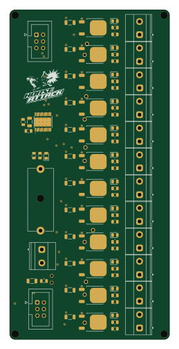
Pwm dc dimmer
61 × 125.5 mm69 parts2LGPL-3.01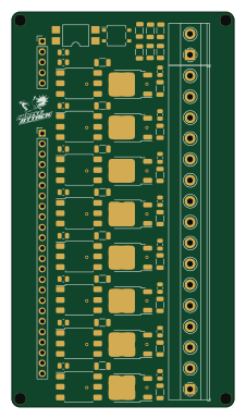
Leading edge ac dimmer
54 × 96 mm57 parts2LGPL-3.01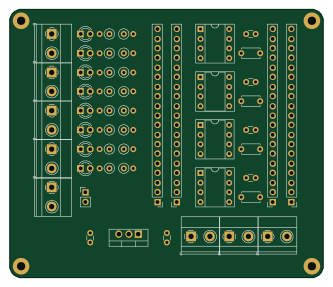
Esp32shield
83 × 71 mm52 parts2LGPL-3.01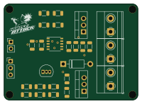
Ac dimmer
50 × 36 mm22 parts2LGPL-3.01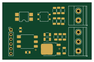
Leading edge ac dimmer.bak
47.6 × 30.5 mm21 parts2LGPL-3.01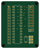
Spi port expander
35 × 43 mm12 parts2LGPL-3.01