
Spi port expander

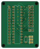
About the Spi port expander PCB
Spi port expander is an open source PCB design by niliha, published on GitHub under the GPL-3.0 license. It is a 2-layer board measuring 35 × 43 mm, with 12 components from 7 distinct parts.
Other key parts include the MCP23S17_SP. By type, the board carries 3 connectors, 3 jumpers, 1 IC and 1 capacitor.
From the project
PCB designs for driving light fixtures like WS28XX LED strips or light bulbs
This is a breakout board for the MCP23S17 16 channel SPI port expander. Using hardware addressing mode, 8 of these port expanders can be driven on a single SPI bus with the same chip select line.
Main components on the Spi port expander
Spi port expander bill of materials (BOM)
12 components, 7 distinct parts.
| Qty | Part | Footprint | Refs |
|---|---|---|---|
| 1 | MCP23S17_SP | DIP-28_W7.62mm | U1 |
| 1 | Conn_01x14_Pin | PinHeader_1x14_P2.54mm_Vertical | J1 |
| 1 | Conn_02x01 | PinHeader_2x01_P2.54mm_Vertical | J3 |
| 1 | Conn_02x08_Odd_Even | PinHeader_2x08_P2.54mm_Vertical | J4 |
| 4 | MountingHole | MountingHole_2.7mm_M2.5 | H1, H2, H3, H4 |
| 3 | SolderJumper_3_Open | SolderJumper-3_P1.3mm_Open_Pad1.0x1.5mm | JP1, JP2, JP3 |
| 1 | 0.1uF | C_Disc_D5.0mm_W2.5mm_P5.00mm | C1 |
Spi port expander design files
The KiCad project lives in the niliha/ravelights-hardware repository on GitHub; these links point at the commit this page was built from.
Spi port expander: common questions
How big is the Spi port expander PCB?
The Spi port expander measures 35 × 43 mm, has 2 copper layers and is 1.6 mm thick.
How many components are on the Spi port expander?
12 components, from 7 distinct parts. The full bill of materials is listed on this page.
Where can I download the Spi port expander design files?
From the niliha/ravelights-hardware repository on GitHub, which has the KiCad layout and the schematic; the links under Design files point to each one.
Can I use the Spi port expander design in my own project?
Yes, under the terms of its GPL-3.0 license, which niliha chose for the repository.
More boards in ravelights-hardware
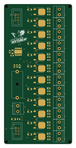
Pwm dc dimmer
61 × 125.5 mm69 parts2LGPL-3.01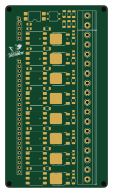
Leading edge ac dimmer
54 × 96 mm57 parts2LGPL-3.01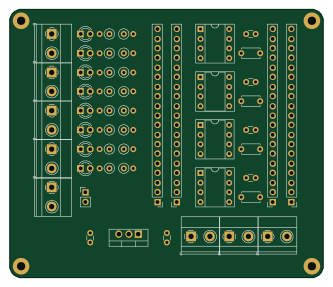
Esp32shield
83 × 71 mm52 parts2LGPL-3.01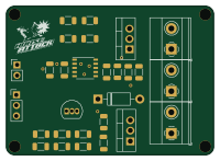
Ac dimmer
50 × 36 mm22 parts2LGPL-3.01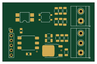
Leading edge ac dimmer.bak
47.6 × 30.5 mm21 parts2LGPL-3.01
Signal booster
18.8 × 18.8 mm19 parts2LGPL-3.01