
Blinder

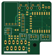
About the Blinder PCB
Blinder is an open source ESP8266 PCB design by nophead, published on GitHub under the GPL-3.0 license. It is a 4-layer board measuring 42 × 45 mm, with 24 components from 17 distinct parts.
Its main chip is the ESP-12F, from the ESP8266 family. Other key parts include the L6203 and 3.3V. By type, the board carries 8 resistors, 5 connectors, 5 capacitors, 3 ICs, 2 switches and 1 diode.
It belongs with the iot & wireless designs in this gallery.
From the project
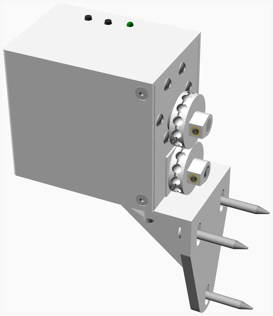
Tasmota roller blind open / close mechanism
Tasmota roller blind open / close mechanism
1. Fit the heatfit insert 1. Add the grub screw
1. Fit the heatfit inserts into the slide. 1. Screw the microswitch to the slide using 10mm M2 cap screws spring washers and plain washers. 1. Solder two wires to the outer pins.
* Turn down the ends of the studding to 5.96mm to fit through the bearings.
1. Fit the heatfit insert 1. Add the grub screw
Main components on the Blinder
Blinder bill of materials (BOM)
24 components, 17 distinct parts — part numbers from the project's BOM.
| Qty | Part | Footprint | Refs |
|---|---|---|---|
| 1 | L6203 | MULTIWATT-11 | IC1 |
| 1 | 3.3V | TinyBuck | U1 |
| 1 | ESP-12F | ESP-12E | U2 |
| 1 | PWR | Molex_KK-254_AE-6410-02A_1x02_P2.54mm_Vertical | J1 |
| 1 | PGM | PinHeader_1x06_P2.54mm_Vertical | J2 |
| 1 | DOWN LIMIT | JST_PH_B3B-PH-K_1x03_P2.00mm_Vertical | J3 |
| 1 | UP LIMIT | JST_PH_B3B-PH-K_1x03_P2.00mm_Vertical | J4 |
| 1 | MOT | JST_PH_B2B-PH-K_1x02_P2.00mm_Vertical | J5 |
| 1 | UP | SW_Tactile_SPST_Angled_PTS645Vx39-2LFS | SW1 |
| 1 | DOWN | SW_Tactile_SPST_Angled_PTS645Vx39-2LFS | SW2 |
| 1 | green | LED_D3.0mm_Horizontal_O1.27mm_Z2.0mm | D1 |
| 2 | 100n | C_0805_2012Metric_Pad1.18x1.45mm_HandSolder | C1, C3 |
| 1 | 220n | C_0805_2012Metric_Pad1.18x1.45mm_HandSolder | C2 |
| 2 | 15n | C_0805_2012Metric_Pad1.18x1.45mm_HandSolder | C4, C5 |
| 5 | 10K | R_0805_2012Metric_Pad1.20x1.40mm_HandSolder | R1, R2, R3, R4, R5 |
| 1 | 2K2 | R_0805_2012Metric_Pad1.20x1.40mm_HandSolder | R6 |
| 2 | 1K | R_0805_2012Metric_Pad1.20x1.40mm_HandSolder | R7, R8 |
Blinder design files
The KiCad project lives in the nophead/Blinder repository on GitHub; these links point at the commit this page was built from.
- LayoutPCB/Blinder/Blinder.kicad_pcb
- SchematicPCB/Blinder/Blinder.kicad_sch
- BOMbom/bom.csv
Blinder: common questions
What microcontroller does the Blinder use?
The Blinder is built around the ESP-12F, from the ESP8266 family.
How big is the Blinder PCB?
The Blinder measures 42 × 45 mm, has 4 copper layers and is 1.6 mm thick.
How many components are on the Blinder?
24 components, from 17 distinct parts, with part numbers taken from the project's own BOM. The full bill of materials is listed on this page.
Where can I download the Blinder design files?
From the nophead/Blinder repository on GitHub, which has the KiCad layout, the schematic and the BOM; the links under Design files point to each one.
Can I use the Blinder design in my own project?
Yes, under the terms of its GPL-3.0 license, which nophead chose for the repository.
Can I test firmware for the Blinder without the hardware?
Yes. HardLabs builds a simulation of the board from its netlist and BOM, so you can run and debug ESP8266 firmware against it before you order a PCB.
Similar boards
 ESP8266
ControllerCircuit
stuartpittaway
75 × 30 mm20 parts2LCC-BY-NC-4.01.1k ESP8266
HASwitchPlate
aderusha
60 × 40 mm8 parts2LMIT738 ESP8266
RatGDO-OpenSource-D1Mini-ESP8266
Kaldek
47.8 × 63.3 mm12 parts2LMIT506 ESP8266
Goatgdo
32.9 × 53.3 mm23 parts2LMIT506 ESP8266
RatGDO-OpenSource-Bare-ESP8266
55 × 82.7 mm20 parts2LMIT506 ESP8266
Iaq board
nkitanov
70.1 × 43.2 mm17 parts2LNo license398