
Load cell

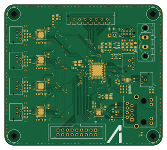
About the Load cell PCB
Load cell is an open source STM32 PCB design by npgo22, published on GitHub. It is a 4-layer board measuring 85 × 76 mm, with 137 components from 40 distinct parts.
Its main chip is the STM32H563RIV6, from the STM32 family. Other key parts include the AP2112K-3.3TRG1, TJA1462ATK/0Z, LAN8742AI-CZ-TR and ADS1261IRHBR. By type, the board carries 69 capacitors, 29 resistors, 13 diodes, 12 connectors, 8 ICs and 3 crystals.
From the project
PCBs for APRL electrical
A board that reads a load cell reading. Typically used for engine thrust measurements.
Main components on the Load cell
Load cell bill of materials (BOM)
137 components, 40 distinct parts.
| Qty | Part | Footprint | Refs |
|---|---|---|---|
| 1 | STM32H563RIV6 | QFN-68-1EP_8x8mm_P0.4mm_EP6.4x6.4mm | U1 |
| 1 | AP2112K-3.3TRG1 AP2112K-3.3 | SOT-23-5 | U2 |
| 1 | TJA1462ATK/0Z TJA1462ATK | HVSON-8-1EP_3x3mm_P0.65mm_EP1.6x2.4mm_ThermalVias | U3 |
| 1 | LAN8742AI-CZ-TR LAN8742AI | VQFN-24-1EP_4x4mm_P0.5mm_EP2.5x2.5mm_ThermalVias | U4 |
| 4 | ADS1261IRHBR ADS1261 | Texas_RHB0032E_VQFN-32-1EP_5x5mm_P0.5mm_EP3.45x3.45mm_ThermalVias | U5, U6, U7, U8 |
| 2 | X1E0000210139 25 MHz | 3225-4P-L | Y1, Y3 |
| 1 | SX3M7.3728M20F30TNN 7.3728 MHz | Oscillator_SCTF_SX3M_3.2x2.5mm | Y2 |
| 1 | Conn_02x01 | PinHeader_1x02_P2.54mm_Vertical | J1 |
| 1 | 503159-0501 Conn_01x05 | Molex_CLIK-Mate_503159-0501_1x05-1MP_P1.50mm_Vertical | J2 |
| 1 | GT-USB-7051A USB_C_Receptacle_USB2.0_16P | USB_C_Receptacle_G-Switch_GT-USB-7051x | J3 |
| 1 | 503159-1501 Conn_01x15 | Molex_CLIK-Mate_503159-1501_1x15-1MP_P1.50mm_Vertical | J4 |
| 1 | Conn_02x09_Counter_Clockwise | IDC-Header_2x09_P2.54mm_Vertical | J5 |
| 1 | MSTBV 2,5/ 2-GF-5,08 Screw_Terminal_01x02 | PhoenixContact_MSTBV_2,5_2-GF-5,08_1x02_P5.08mm_Vertical_ThreadedFlange_MountHole | J6 |
| 1 | 503159-0301 Conn_01x03 | Molex_CLIK-Mate_503159-0301_1x03-1MP_P1.50mm_Vertical | J7 |
| 1 | HY951180A Vertical Ethernet | RJ45_Hanrun_HY951180A_Vertical | J8 |
| 4 | 503159-0401 Conn_01x04 | Molex_CLIK-Mate_503159-0401_1x04-1MP_P1.50mm_Vertical | J9, J10, J11, J12 |
| 2 | 0805L050WR 500mA | Fuse_0805_2012Metric | F1, F2 |
| 1 | SKRPANE010 | SKRPANE010 | SW1 |
| 5 | LED | LED_0603 | D1, D2, D3, D4, D5 |
| 8 | SMF7V0A-E3-18 SMF7V0A | D_SMF | D6, D7, D8, D9, D10, D11, D12, D13 |
Show 20 more
| Qty | Part | Footprint | Refs |
|---|---|---|---|
| 15 | GRM188D72A105KE01 1uF | C_0603 | C1, C19, C24, C30, C33, C38, C40, C43 +7 |
| 20 | GRM188R72A104KA35 100nF | C_0603 | C2, C3, C4, C5, C6, C7, C12, C20 +12 |
| 4 | GRM1885C2E150FW07 15pF | C_0603 | C8, C9, C28, C29 |
| 2 | GRM188R71A225KE15 2.2uF | C_0603 | C10, C11 |
| 6 | GRM21BZ71A226ME15 22uF | C_0805 | C13, C14, C15, C16, C17, C18 |
| 1 | GRM1885C1H471JA01 470pF | C_0603 | C25 |
| 1 | GRM188R71H224KAC4 220nF | C_0603 | C27 |
| 8 | GRM1885C1H102FA01 1nF | C_0603 | C34, C36, C44, C46, C54, C56, C64, C66 |
| 4 | GRM1885C1H103JA01 10nF | C_0603 | C35, C45, C55, C65 |
| 4 | GRM1885C1H472JA01 4.7nF | C_0603 | C37, C47, C57, C67 |
| 4 | GRM188R61A106KE69 10uF | C_0603 | C39, C49, C59, C69 |
| 2 | RC0603FR-074K7L 4.7k | R_0603 | R1, R2 |
| 9 | RC0603FR-0710KL 10k | R_0603 | R3, R4, R5, R6, R7, R8, R9, R17 +1 |
| 1 | RC0603FR-0722RL 22R | R_0603 | R10 |
| 1 | AC0603FR-07120RL 120R | R_0603 | R11 |
| 1 | RC0603FR-071K5L 1.5k | R_0603 | R12 |
| 4 | RC0603FR-0747RL 47R | R_0603 | R13, R14, R15, R16 |
| 1 | RT0603BRD0712K1L 12.1k | R_0603 | R18 |
| 2 | RC0603FR-07330RL 330R | R_0603 | R20, R21 |
| 8 | RT0603BRD071KL 1k | R_0603 | R22, R23, R24, R25, R26, R27, R28, R29 |
Load cell design files
The KiCad project lives in the npgo22/APRL-Electrical repository on GitHub; these links point at the commit this page was built from.
Load cell: common questions
What microcontroller does the Load cell use?
The Load cell is built around the STM32H563RIV6, from the STM32 family.
How big is the Load cell PCB?
The Load cell measures 85 × 76 mm, has 4 copper layers and is 1.6 mm thick.
How many components are on the Load cell?
137 components, from 40 distinct parts. The full bill of materials is listed on this page.
Where can I download the Load cell design files?
From the npgo22/APRL-Electrical repository on GitHub, which has the KiCad layout and the schematic; the links under Design files point to each one.
Can I use the Load cell design in my own project?
The repository has no license, so all rights stay with npgo22. Use it as a reference, and ask the author before reusing the design.
Can I test firmware for the Load cell without the hardware?
Yes. HardLabs builds a simulation of the board from its netlist and BOM, so you can run and debug STM32 firmware against it before you order a PCB.
More boards in APRL-Electrical
 STM32
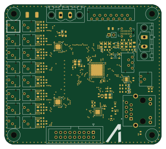
STM32Pressuretransducers
85 × 76 mm216 parts4LNo license0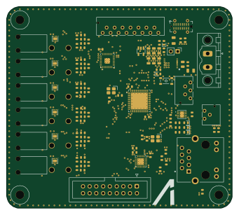 STM32
STM32Thermocouples
85 × 76 mm163 parts4LNo license0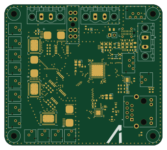 STM32
STM32Valvedrivers
85 × 76 mm148 parts4LNo license0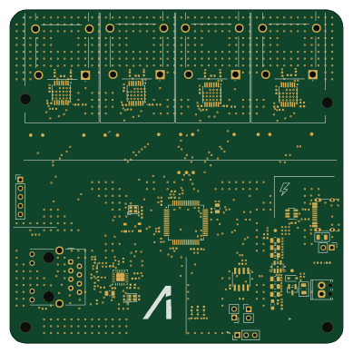 STM32
STM32Thermocouple Board
97 × 97.1 mm117 parts4LNo license0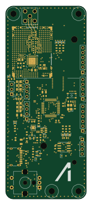 STM32
STM32Chickenstick
42 × 100 mm96 parts4LNo license0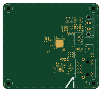 STM32
STM32Ali template
85 × 76 mm66 parts4LNo license0
GPS Module
43 × 34 mm24 parts4LNo license0
Similar boards
 STM32
STM32LumenPnP Motherboard
opulo-inc
149 × 95 mm296 parts4LCC-BY-SA-4.03.7k STM32
STM32AxxSolder
AxxAxx
39 × 82.5 mm122 parts2LGPL-3.01.7k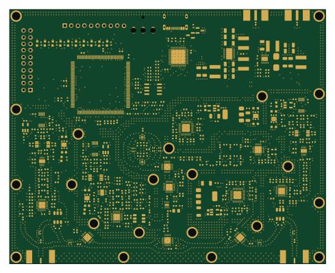 STM32
STM32LibreVNA
jankae
122 × 98 mm592 parts6LGPL-3.01.6k STM32
STM32AIOC
skuep
21 × 31.5 mm47 parts2LMIT1.4k STM32
STM32Ferris
pierrechevalier83
208.8 × 86.8 mm102 parts2LSHL-2.11.3k STM32
STM32176 pin board
rusefi
61.8 × 73.2 mm76 parts2LGPL-3.01.2k