
2026 12 2Wheel Balance Robot v1

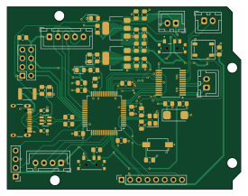
About the 2026 12 2Wheel Balance Robot v1 PCB
2026 12 2Wheel Balance Robot v1 is an open source STM32 PCB design by nruth633, published on GitHub. It is a 2-layer board measuring 68.6 × 53.4 mm, with 56 components from 34 distinct parts.
Its main chip is the STM32F401RBTx, from the STM32 family. Other key parts include the TB6612FNG, LD1117S50TR_SOT223, USBLC6-2SC6 and LD1117S33TR_SOT223. By type, the board carries 22 capacitors, 10 resistors, 9 connectors, 5 ICs, 5 diodes and 3 switches.
It belongs with the robotics & motion designs in this gallery.
From the project
STM32F401 robot on a custom KiCad board, driven from a phone through an ESP8266
A three-wheel robot on an STM32F401 control board I designed in KiCad and soldered by hand. An ESP8266 runs its own WiFi access point and serves a control page, so you can drive it from a phone browser. Button presses go over a WebSocket to the ESP8266, which passes them to the STM32 over UART. Roll and pitch from the MPU6050 are sent back to the page. The STM32 firmware was provided by my professor; I built it and flashed the board with STM32CubeIDE and STM32CubeProgrammer.
Main components on the 2026 12 2Wheel Balance Robot v1
2026 12 2Wheel Balance Robot v1 bill of materials (BOM)
56 components, 34 distinct parts.
| Qty | Part | Footprint | Refs |
|---|---|---|---|
| 1 | STM32F401RBTx | LQFP-64_10x10mm_P0.5mm | U1 |
| 1 | TB6612FNG | SSOP-24_5.3x8.2mm_P0.65mm | U2 |
| 1 | LD1117S50TR_SOT223 | SOT-223-3_TabPin2 | U3 |
| 1 | USBLC6-2SC6 | SOT-23-6 | U5 |
| 1 | LD1117S33TR_SOT223 | SOT-223-3_TabPin2 | U6 |
| 1 | 16MHz ABRACON | Crystal_SMD_Abracon_ABM8G-4Pin_3.2x2.5mm | Y3 |
| 1 | Conn_01x04 | PinHeader_1x04_P2.54mm_Vertical | J1 |
| 1 | CONN_MPU6050 | PinSocket_1x08_P2.54mm_Vertical | J2 |
| 1 | USB_C_Receptacle_USB2.0_14P Same Sky | USB_C_Receptacle_HCTL_HC-TYPE-C-16P-01A | J3 |
| 1 | ESP_Conn | PinSocket_2x04_P2.54mm_Vertical | J4 |
| 1 | BATT_CONN | JST_XH_B2B-XH-A_1x02_P2.50mm_Vertical | J5 |
| 1 | M1_CONN | JST_XH_B2B-XH-A_1x02_P2.50mm_Vertical | J6 |
| 1 | M2_CONN | JST_XH_B2B-XH-A_1x02_P2.50mm_Vertical | J7 |
| 1 | ENCODER_CONN | JST_XH_B4B-XH-A_1x04_P2.50mm_Vertical | J8 |
| 1 | MT6701_CONN | JST_XH_B5B-XH-A_1x05_P2.50mm_Vertical | J9 |
| 1 | PTCSMD | Fuse_1812_4532Metric | F1 |
| 1 | REGULATOR_SWITCH | SW_SLW-66527511-SMT-TR | S3 |
| 1 | RST_SWITCH | SW_SLW-66527511-SMT-TR | S4 |
| 1 | SW_uP_Reset Wurth Elektronik | SW_uP_Reset | SW2 |
| 1 | WS2812B | LED_WS2812B_PLCC4_5.0x5.0mm_P3.2mm | D1 |
Show 14 more
| Qty | Part | Footprint | Refs |
|---|---|---|---|
| 1 | USB_LED | LED_0805_2012Metric_Pad1.15x1.40mm_HandSolder | D2 |
| 1 | 3V3_LED | LED_0805_2012Metric_Pad1.15x1.40mm_HandSolder | D3 |
| 1 | USER_LED | LED_0805_2012Metric_Pad1.15x1.40mm_HandSolder | D4 |
| 1 | 5V_LED | LED_0805_2012Metric_Pad1.15x1.40mm_HandSolder | D5 |
| 12 | 0.1uF | C_0805_2012Metric_Pad1.18x1.45mm_HandSolder | C1, C2, C3, C4, C6, C8, C13, C14 +4 |
| 1 | 2.2uF | C_0805_2012Metric_Pad1.18x1.45mm_HandSolder | C7 |
| 1 | 10uF | CP_EIA-6032-28_Kemet-C_HandSolder | C9 |
| 5 | 10uF KEMET | C_0805_2012Metric_Pad1.18x1.45mm_HandSolder | C15, C16, C18, C23, C25 |
| 2 | 22p KYOCERA AVX | C_0805_2012Metric_Pad1.18x1.45mm_HandSolder | C19, C20 |
| 1 | 0.01uF KYOCERA AVX | C_0805_2012Metric_Pad1.18x1.45mm_HandSolder | C21 |
| 4 | 1k | R_0805_2012Metric_Pad1.20x1.40mm_HandSolder | R1, R6, R9, R10 |
| 2 | 10k | R_0805_2012Metric_Pad1.20x1.40mm_HandSolder | R2, R17 |
| 2 | 22R | R_0805_2012Metric_Pad1.20x1.40mm_HandSolder | R3, R4 |
| 2 | 5.1k Vishay / Dale | R_0603_1608Metric_Pad0.98x0.95mm_HandSolder | R7, R8 |
2026 12 2Wheel Balance Robot v1 design files
The KiCad project lives in the nruth633/3-wheel-balancing-robot repository on GitHub; these links point at the commit this page was built from.
2026 12 2Wheel Balance Robot v1: common questions
What microcontroller does the 2026 12 2Wheel Balance Robot v1 use?
The 2026 12 2Wheel Balance Robot v1 is built around the STM32F401RBTx, from the STM32 family.
How big is the 2026 12 2Wheel Balance Robot v1 PCB?
The 2026 12 2Wheel Balance Robot v1 measures 68.6 × 53.4 mm, has 2 copper layers and is 1.6 mm thick.
How many components are on the 2026 12 2Wheel Balance Robot v1?
56 components, from 34 distinct parts. The full bill of materials is listed on this page.
Where can I download the 2026 12 2Wheel Balance Robot v1 design files?
From the nruth633/3-wheel-balancing-robot repository on GitHub, which has the KiCad layout and the schematic; the links under Design files point to each one.
Can I use the 2026 12 2Wheel Balance Robot v1 design in my own project?
The repository has no license, so all rights stay with nruth633. Use it as a reference, and ask the author before reusing the design.
Can I test firmware for the 2026 12 2Wheel Balance Robot v1 without the hardware?
Yes. HardLabs builds a simulation of the board from its netlist and BOM, so you can run and debug STM32 firmware against it before you order a PCB.
More boards in 3-wheel-balancing-robot
Similar boards
 STM32
STM32LumenPnP Motherboard
opulo-inc
149 × 95 mm296 parts4LCC-BY-SA-4.03.7k STM32
STM32Type c
google
188 × 30 mm17 parts2LApache-2.02.9k STM32
STM32Main panel
234 × 84 mm26 parts4LApache-2.02.9k STM32
STM32Base
52.3 × 52.3 mm36 parts2LApache-2.02.9k STM32
STM32Type a
150 × 30 mm14 parts2LApache-2.02.9k STM32
STM32Type e
140.5 × 30 mm13 parts2LApache-2.02.9k