
Gyraf output

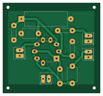
About the Gyraf output PCB
Gyraf output is an open source PCB design by oletizi, published on GitHub. It is a 2-layer board measuring 84.5 × 78.7 mm, with 12 components from 12 distinct parts.
Other key parts include the ECC81. By type, the board carries 4 connectors, 4 resistors, 3 capacitors and 1 IC.
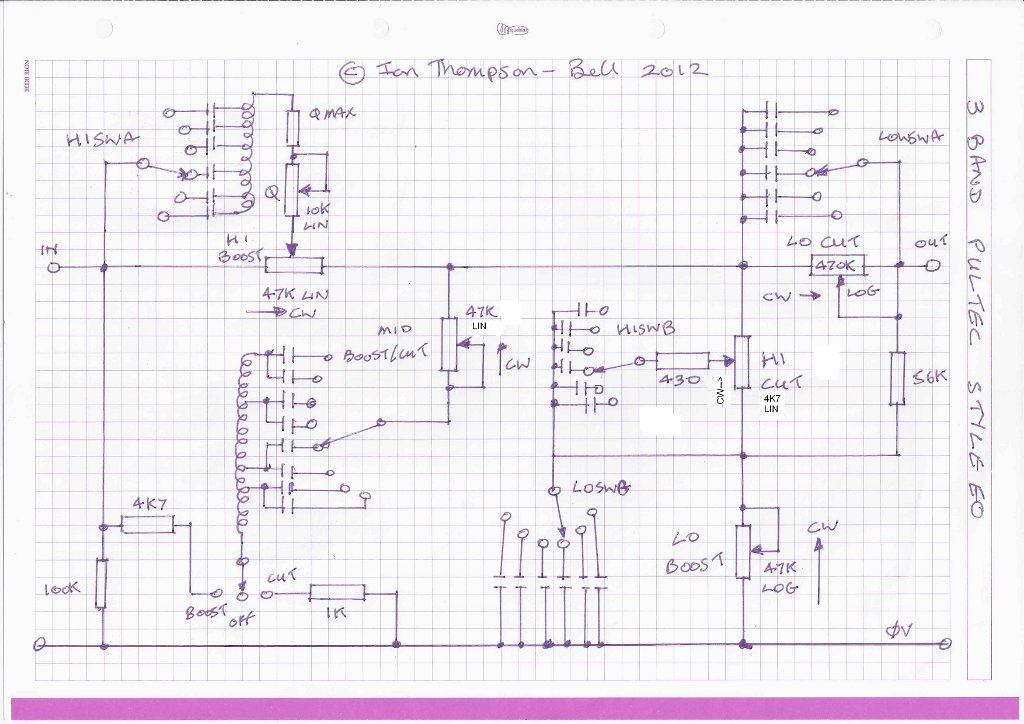
Main components on the Gyraf output
Gyraf output bill of materials (BOM)
12 components, 12 distinct parts.
| Qty | Part | Footprint | Refs |
|---|---|---|---|
| 1 | ECC81 | BELTON_VT9-PT Fat Pad | U1 |
| 1 | Input | TerminalBlock_Phoenix_MKDS-1,5-2_1x02_P5.00mm_Horizontal Fat Pad | J1 |
| 1 | Output | TerminalBlock_Phoenix_MKDS-1,5-2_1x02_P5.00mm_Horizontal Fat Pad | J2 |
| 1 | B+ | TerminalBlock_Phoenix_MKDS-1,5-2_1x02_P5.00mm_Horizontal Fat Pad | J3 |
| 1 | Heater | TerminalBlock_Phoenix_MKDS-1,5-2_1x02_P5.00mm_Horizontal Fat Pad | J4 |
| 1 | 4.7uF | C_Axial_L12.0mm_D8.5mm_P15.00mm_Horizontal Fat Pad | C1 |
| 1 | 100nF | C_Axial_L12.0mm_D8.5mm_P15.00mm_Horizontal Fat Pad | C2 |
| 1 | 470uF 16V | CP_Axial_L37.0mm_D13.0mm_P43.00mm_Horizontal_Fat_Pad | C3 |
| 1 | 1K5 | R_Axial_DIN0411_L9.9mm_D3.6mm_P12.70mm_Horizontal Fat Pad | R1 |
| 1 | 470R | R_Axial_DIN0411_L9.9mm_D3.6mm_P12.70mm_Horizontal Fat Pad | R2 |
| 1 | 1M | R_Axial_DIN0411_L9.9mm_D3.6mm_P12.70mm_Horizontal Fat Pad | R3 |
| 1 | 1K | R_Axial_DIN0411_L9.9mm_D3.6mm_P12.70mm_Horizontal Fat Pad | R4 |
Gyraf output design files
The KiCad project lives in the oletizi/multi-channel-preamp repository on GitHub; these links point at the commit this page was built from.
Gyraf output: common questions
How big is the Gyraf output PCB?
The Gyraf output measures 84.5 × 78.7 mm, has 2 copper layers and is 1.6 mm thick.
How many components are on the Gyraf output?
12 components, from 12 distinct parts. The full bill of materials is listed on this page.
Where can I download the Gyraf output design files?
From the oletizi/multi-channel-preamp repository on GitHub, which has the KiCad layout and the schematic; the links under Design files point to each one.
Can I use the Gyraf output design in my own project?
The repository has no license, so all rights stay with oletizi. Use it as a reference, and ask the author before reusing the design.
More boards in multi-channel-preamp
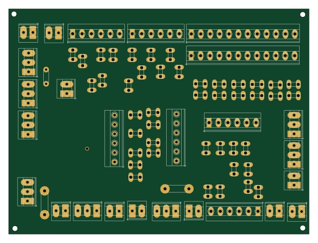
Pultec 3-Band EQ
159.5 × 120 mm73 parts2LNo license0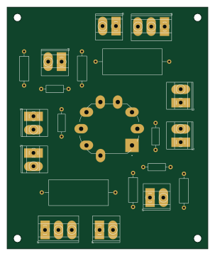
Multi channel preamp
74.9 × 90.2 mm21 parts2LNo license0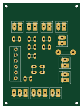
Pultec boost high
66.7 × 88.9 mm21 parts2LNo license0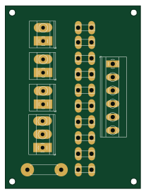
Pultec cut high
50.8 × 68.6 mm16 parts2LNo license0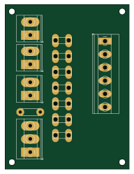
Pultec cut low
47 × 62.2 mm13 parts2LNo license0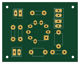
Tapeop output
80 × 63.5 mm11 parts2LNo license0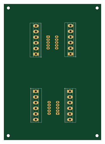
Pultec Inductor Board
86 × 120 mm6 parts2LNo license0