
USBtoUART

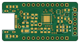
About the USBtoUART PCB
USBtoUART is an open source PCB design by paclema, published on GitHub. It is a 2-layer board measuring 39.9 × 20.7 mm, with 32 components from 24 distinct parts.
Other key parts include the CP2102N-Axx-xQFN28 and XC6220B331ER. By type, the board carries 13 resistors, 7 capacitors, 5 diodes, 4 connectors, 2 ICs and 1 transistor.
It belongs with the usb & debug tools, power & battery and dev boards & breakouts designs in this gallery.
From the project
Compact USB-to-UART board (CP2102N) with an LDO (XC6220B331ER) for 3.3V power output
A compact USB-C to UART bridge board based on the Silicon Labs CP2102N chip and featuring a dedicated XC6220B331ER LDO regulator, designed for debugging, programming, and serial communication with microcontrollers and embedded systems.
Why this board? Unlike typical USB-to-UART bridges, this board features a dedicated LDO regulator that supplies up to 1A at 3.3V, ensuring stable power delivery to the target board while providing reliable data communication.
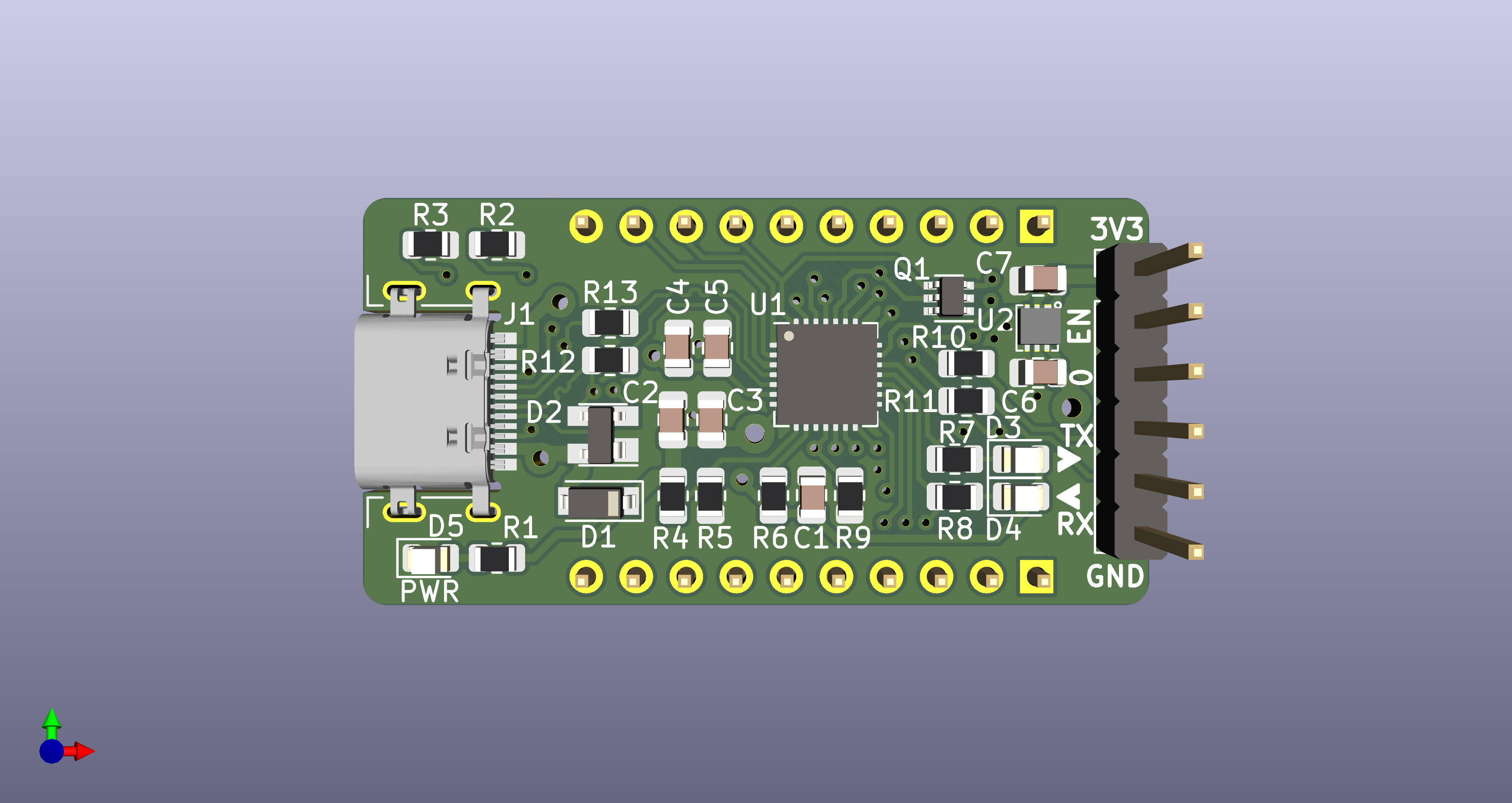
Main components on the USBtoUART
USBtoUART bill of materials (BOM)
32 components, 24 distinct parts.
| Qty | Part | Footprint | Refs |
|---|---|---|---|
| 1 | CP2102N-Axx-xQFN28 | QFN-28-1EP_5x5mm_P0.5mm_EP3.35x3.35mm_ThermalVias | U1 |
| 1 | XC6220B331ER | USP-6C | U2 |
| 1 | MUN5211DW1 | SOT-363_SC-70-6 | Q1 |
| 1 | USB_C_Receptacle_USB2.0 | USB_C_Receptacle_Molex_216990-001 | J1 |
| 1 | PORT1 | PinHeader_1x10_P2.54mm_Vertical | J2 |
| 1 | UART0 | PinHeader_1x06_P2.54mm_Vertical | J3 |
| 1 | PORT2 | PinHeader_1x10_P2.54mm_Vertical | J4 |
| 1 | SS14/1N5819/S4/BAT760-7 | SOD-123EP | D1 |
| 1 | SP0503BAHT | SOT-143 | D2 |
| 1 | TX | LED_0805_2012Metric | D3 |
| 1 | RX | LED_0805_2012Metric | D4 |
| 1 | PWR | LED_0805_2012Metric | D5 |
| 3 | 0.1uF | C_0805_2012Metric | C1, C3, C4 |
| 3 | 4.7uF | C_0805_2012Metric | C2, C5, C7 |
| 1 | 22uF | C_0805_2012Metric | C6 |
| 1 | 2.2K | R_0805_2012Metric | R1 |
| 2 | 5.1K | R_0805_2012Metric | R2, R3 |
| 1 | 22.1K | R_0805_2012Metric | R4 |
| 1 | 47.5K | R_0805_2012Metric | R5 |
| 1 | 4.7K | R_0805_2012Metric | R6 |
Show 4 more
| Qty | Part | Footprint | Refs |
|---|---|---|---|
| 2 | 1K | R_0805_2012Metric | R7, R8 |
| 1 | 10K | R_0805_2012Metric | R9 |
| 2 | 470R | R_0805_2012Metric | R10, R11 |
| 2 | 22R | R_0805_2012Metric | R12, R13 |
USBtoUART design files
The KiCad project lives in the paclema/USBtoUART repository on GitHub; these links point at the commit this page was built from.
- LayoutUSBtoUART.kicad_pcb
- SchematicUSBtoUART.kicad_sch
USBtoUART: common questions
How big is the USBtoUART PCB?
The USBtoUART measures 39.9 × 20.7 mm, has 2 copper layers and is 1.6 mm thick.
How many components are on the USBtoUART?
32 components, from 24 distinct parts. The full bill of materials is listed on this page.
Where can I download the USBtoUART design files?
From the paclema/USBtoUART repository on GitHub, which has the KiCad layout and the schematic; the links under Design files point to each one.
Can I use the USBtoUART design in my own project?
The repository has no license, so all rights stay with paclema. Use it as a reference, and ask the author before reusing the design.
Similar boards

EinkPDA screen
TalismanDesign
95 × 54 mm27 parts2LApache-2.02.0k
Stack chan
stack-chan
50 × 50 mm33 parts2LApache-2.01.7k
Display Carrier
AxxAxx
35.6 × 58.2 mm5 parts2LGPL-3.01.7k
88 Pin Vag Breakout
rusefi
142 × 58 mm91 parts2LGPL-3.01.2k
Breakout 60pin EEC-IV
139.7 × 62.2 mm15 parts2LGPL-3.01.2k
Eecv breakout
140.8 × 53.7 mm9 parts4LGPL-3.01.2k