
TransimpedanceAmplifier

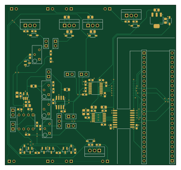
About the TransimpedanceAmplifier PCB
TransimpedanceAmplifier is an open source PCB design by philipturner, published on GitHub under the MIT license. It is a 2-layer board measuring 92.5 × 86.5 mm, with 95 components from 42 distinct parts.
Other key parts include the LM7905, -5V, 5%, LM7805, 5V, 5%, OPA828, AD8615 and OP37GPZ. By type, the board carries 38 capacitors, 19 resistors, 13 ICs, 12 connectors, 11 diodes and 2 transistors.
It belongs with the audio designs in this gallery.
From the project
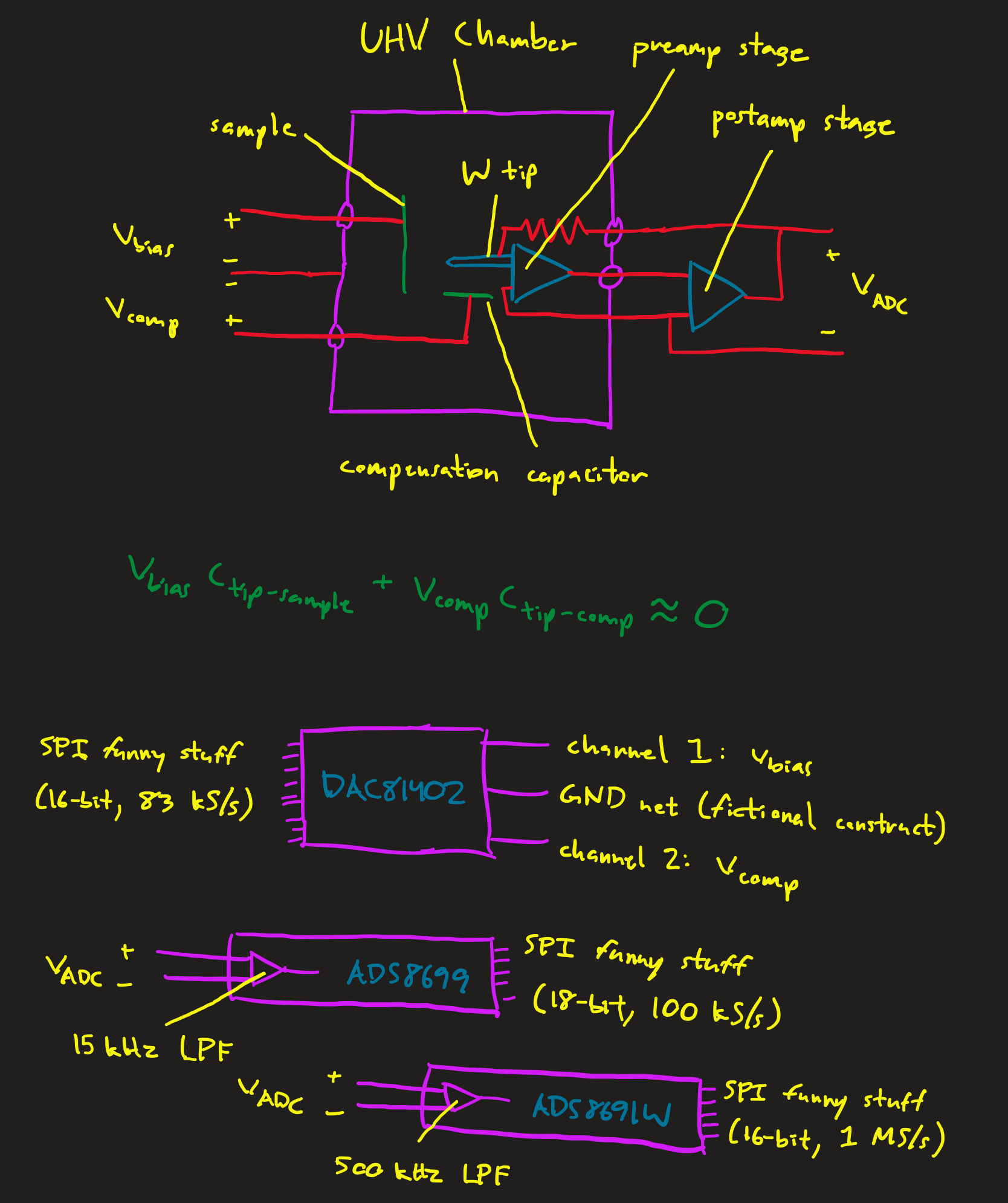
Objective: Gather as much data as possible about the TIA sensor of an STM, using both theory and experiment.
Objective: Gather as much data as possible about the TIA sensor of an STM, using both theory and experiment.
Deadline: September 30, 2025 for the first physical prototype
Three simulation tasks, in chronological order 1) Understand/simulate why coarse tip approach takes so long - Understand specific algorithms for moving the coarse motor (approach & retract) without frictional backlash causing a tip crash - Understand maximum speeds of piezo motors 2) Simulate imperfect DAC-driven cancellation with a fixed value compensation capacitor - Use the tip-sample capacitance of a plausible…
Main components on the TransimpedanceAmplifier
TransimpedanceAmplifier bill of materials (BOM)
95 components, 42 distinct parts.
| Qty | Part | Footprint | Refs |
|---|---|---|---|
| 1 | LM7905, -5V, 5% | TO-220 | U1 |
| 2 | LM7805, 5V, 5% | TO-220 | U2, U8 |
| 1 | OPA828 | SOIC-8 | U3 |
| 1 | AD8615 | AD8615 | U4 |
| 1 | OP37GPZ | PDIP-8 | U5 |
| 1 | LM7915, -15V, 5% | TO-220 | U6 |
| 1 | LM7815, 15V, 5% | TO-220 | U7 |
| 1 | TLV76133, 3.3V, 1% | SOT-223 | U9 |
| 1 | DAC81401 | DAC81401 | U10 |
| 2 | ISO7641FM | ISO7641FM | U11, U12 |
| 1 | ADS8699 | ADS8699 | U13 |
| 1 | Q_PNP | SOT-23 | Q1 |
| 1 | Q_NPN | SOT-23 | Q2 |
| 2 | Conn_01x02_Socket | PinSocket_1x2 | J1, J2 |
| 1 | Conn_01x03_Pin | PinHeader_1x3 | J3 |
| 7 | Conn_01x02_Pin | PinHeader_1x2 | J4, J5, J6, J7, J8, J9, J10 |
| 2 | Conn_01x24_Socket | PinSocket_1x24 | J11, J14 |
| 6 | D_Schottky | SOD-123 | D1, D2, D8, D9, D10, D11 |
| 1 | 3.3V, 1% | SOT-23 | D3 |
| 2 | D | SOD-123 | D4, D5 |
Show 22 more
| Qty | Part | Footprint | Refs |
|---|---|---|---|
| 2 | 10V, 1% | SOT-23 | D6, D7 |
| 4 | 220 nF, 0603 | CAPC0603 | C1, C17, C21, C25 |
| 11 | 100 nF, 0603 | CAPC0603 | C2, C6, C7, C15, C16, C18, C23, C30 +3 |
| 6 | 1 uF, 0805 | CAPC0805 | C3, C4, C19, C20, C22, C24 |
| 1 | 2 nF, 1% | CAPC0603 | C9 |
| 1 | 180 pF, 1% | CAPC0603 | C10 |
| 9 | 1 uF, 0603 | CAPC0603 | C11, C12, C26, C27, C28, C29, C35, C36 +1 |
| 6 | 10 uF, 0805 | CAPC0805 | C13, C14, C34, C37, C38, C40 |
| 1 | 4.7k, 1% | RESC0603 | R1 |
| 1 | 100M, 5% | RESC0805 | R2 |
| 1 | 330M, 5% | RESC0805 | R3 |
| 1 | 1.3k, 1% | RESC0603 | R4 |
| 1 | 10k, 10% | Bourns_3296Y | R5 |
| 1 | 200k, 10% | Bourns_3296Y | R6 |
| 1 | 47k, 10% | Bourns_3296Y | R7 |
| 1 | 100, 1% | RESC0603 | R8 |
| 1 | 220, 1% | RESC0603 | R9 |
| 1 | 523, 1% | RESC0603 | R10 |
| 1 | 1k, 10% | Bourns_3296Y | R11 |
| 3 | 1k, 1% | RESC0603 | R12, R14, R15 |
| 1 | 15k, 1% | RESC0603 | R13 |
| 4 | 10k, 1% | RESC0603 | R16, R17, R18, R19 |
TransimpedanceAmplifier design files
The KiCad project lives in the philipturner/transimpedance-amplifier repository on GitHub; these links point at the commit this page was built from.
TransimpedanceAmplifier: common questions
How big is the TransimpedanceAmplifier PCB?
The TransimpedanceAmplifier measures 92.5 × 86.5 mm, has 2 copper layers and is 1.6256 mm thick.
How many components are on the TransimpedanceAmplifier?
95 components, from 42 distinct parts. The full bill of materials is listed on this page.
Where can I download the TransimpedanceAmplifier design files?
From the philipturner/transimpedance-amplifier repository on GitHub, which has the KiCad layout and the schematic; the links under Design files point to each one.
Can I use the TransimpedanceAmplifier design in my own project?
Yes, under the terms of its MIT license, which philipturner chose for the repository.
More boards in transimpedance-amplifier
Similar boards
KLOR
GEIGEIGEIST
160.2 × 118.3 mm79 parts2LGPL-3.01.2k
ButtonsLEDs
shanteacontrols
390 × 37 mm82 parts2LApache-2.0956
USB
52 × 12.6 mm6 parts2LApache-2.0956
Pots
390 × 93 mm75 parts2LApache-2.0956
PicoGUS Hand386
polpo
29.2 × 75.2 mm43 parts4LGPL-2.0800
Snark barker
schlae
231.1 × 106.7 mm193 parts2LNo license687