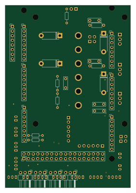
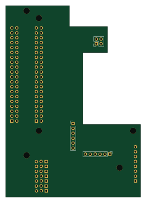
Board0.1-RPi0

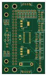
About the Board0.1-RPi0 PCB
Board0.1-RPi0 is an open source PCB design by Plymouth-Sailboat, published on GitHub under the GPL-3.0 license. It is a 2-layer board measuring 39.4 × 65.4 mm, with 41 components from 17 distinct parts.
Other key parts include the LD1117S50TR_SOT223, L7805 and MCP3008. By type, the board carries 29 connectors, 5 capacitors, 4 ICs, 2 diodes and 1 inductor.
From the project
Mechanical documents of the sailboat - Electronic Board and 3D Parts
This repository lists all the mechanical documents of the sailboat - Electronic Board and 3D Parts. It is used in conjunction with the Arduino Repository and the Raspberry Pi Repository. This project was done by Ulysse Vautier for his PhD in Autonomous Sailboat Navigation System at the University of Plymouth.
A complete tutorial is available on the wiki.
The goal of such a project is to make an affordable, accessible and expandable control box to transform a RC sailboat into an autonomous Sailboat easily. The control box costs £86 to make. Once connected to the different sensors and…

Main components on the Board0.1-RPi0
Board0.1-RPi0 bill of materials (BOM)
41 components, 17 distinct parts — part numbers from the project's BOM.
| Qty | Part | Footprint | Refs |
|---|---|---|---|
| 2 | LD1117S50TR_SOT223 | SOT-223-3_TabPin2 | U1, U2 |
| 1 | L7805 | TO-220-3_Vertical | U3 |
| 1 | MCP3008 | SOIC-16_3.9x9.9mm_Pitch1.27mm | U4 |
| 2 | Conn_01x02 | BAT-CONN | J1, J9 |
| 1 | Conn_02x20_Odd_Even | Pin_Header_Straight_2x20_Pitch2.54mm | J2 |
| 7 | Conn_01x03 | Pin_Header_Straight_1x03_Pitch2.54mm | J3, J4, J5, J6, J7, J8, J10 |
| 4 | Conn_01x03_Male | Pin_Header_Angled_1x03_Pitch2.54mm | J11, J12, J13, J14 |
| 6 | Conn_01x04 | JST_PH_S4B-PH-K_04x2.00mm_Angled | J15, J16, J17, J18, J31, J32 |
| 3 | Conn_01x03 | JST_PH_S3B-PH-K_03x2.00mm_Angled | J19, J20, J24 |
| 2 | Conn_01x02 | JST_PH_S2B-PH-K_02x2.00mm_Angled | J21, J22 |
| 4 | Conn_01x02 | Pin_Header_Straight_1x02_Pitch2.54mm | J34, J35, J36, J37 |
| 1 | D_Schottky_Small | D_1206 | D1 |
| 1 | D_Schottky | D_5W_P10.16mm_Horizontal | D4 |
| 1 | 3.3uH | L_0603 | L1 |
| 2 | 100nF | C_0603 | C1, C2 |
| 1 | 0.33uF | C_0603 | C3 |
| 2 | 10uF | C_0603 | C4, C5 |
Board0.1-RPi0 design files
The KiCad project lives in the Plymouth-Sailboat/Sailboat-Meca repository on GitHub; these links point at the commit this page was built from.
Board0.1-RPi0: common questions
How big is the Board0.1-RPi0 PCB?
The Board0.1-RPi0 measures 39.4 × 65.4 mm, has 2 copper layers and is 1.6 mm thick.
How many components are on the Board0.1-RPi0?
41 components, from 17 distinct parts, with part numbers taken from the project's own BOM. The full bill of materials is listed on this page.
Where can I download the Board0.1-RPi0 design files?
From the Plymouth-Sailboat/Sailboat-Meca repository on GitHub, which has the KiCad layout and the BOM; the links under Design files point to each one.
Can I use the Board0.1-RPi0 design in my own project?
Yes, under the terms of its GPL-3.0 license, which Plymouth-Sailboat chose for the repository.