
PortableTerminal

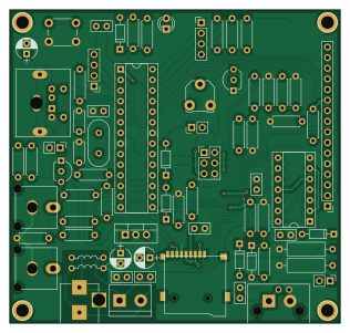
About the PortableTerminal PCB
PortableTerminal is an open source AVR/Arduino PCB design by profdc9, published on GitHub. It is a 2-layer board measuring 79 × 75 mm, with 76 components from 33 distinct parts.
Its main chip is the ATMEGA328P-PU, from the AVR/Arduino family. Other key parts include the LM7805_TO220, LCD-016N002L, MicroSD_SPI_CD and 74HC74. By type, the board carries 29 resistors, 13 connectors, 13 capacitors, 7 diodes, 5 ICs and 3 jumpers.
It belongs with the rf & radio, audio and displays & leds designs in this gallery.
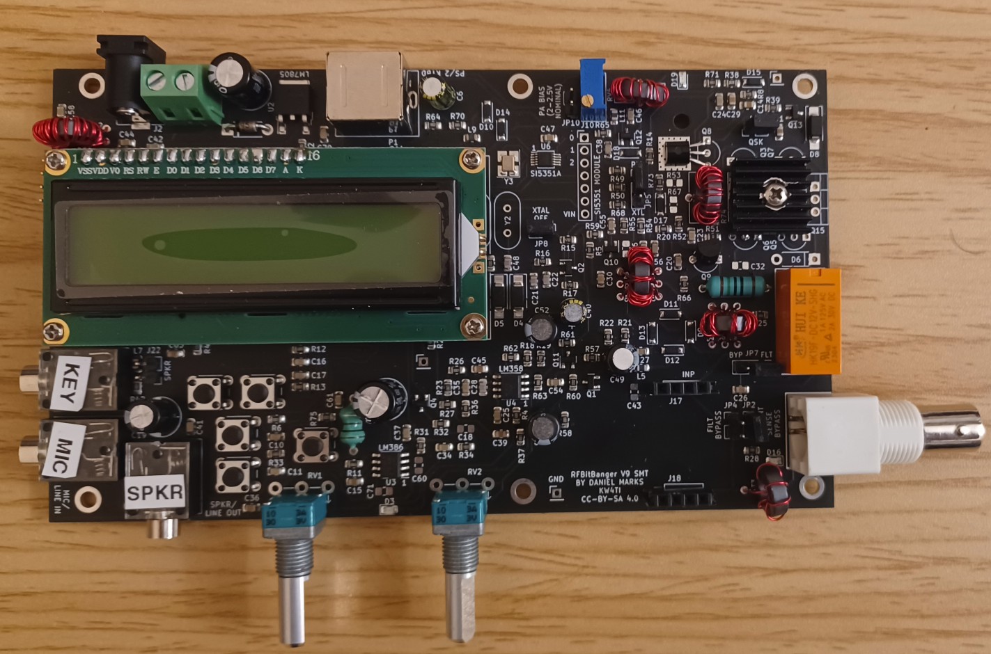
From the project
A QRP digital transceiver created from readily available parts for off-the-grid maintenance
A presentation presented at the 2023 QSO Today conference on the RFBitBanger can be viewed on Youtube here.
A single band double-sideband radio, with the band changed by pluggable external filters on 20 m to 80 m. A double-balanced ring mixer is used to provide good rejection of strong stations while not requiring any custom ICs such as SA612 or FST3253. The mixer has strong drive to reduce nonlinearity. Can be assembled and operated by a properly licensed individual that may not have a great deal of electronics experience or experience at making HF contacts. The radio is made from readily…
Main components on the PortableTerminal
PortableTerminal bill of materials (BOM)
76 components, 33 distinct parts.
| Qty | Part | Footprint | Refs |
|---|---|---|---|
| 1 | LM7805_TO220 | TO-220-3_Vertical | U1 |
| 1 | ATMEGA328P-PU | DIP-28_W7.62mm_Socket | U2 |
| 1 | LCD-016N002L | Pin_Header_Straight_1x16_Pitch2.54mm | U3 |
| 1 | MicroSD_SPI_CD | GCT-MEM2055-00-190-01-A | U4 |
| 1 | 74HC74 | DIP-14_W7.62mm_Socket | U5 |
| 2 | 2N3904 | TO-92_Inline_Wide | Q1, Q2 |
| 1 | Crystal | Crystal_HC49-U_Vertical | Y1 |
| 1 | Barrel_Jack | BARREL_JACK | J1 |
| 4 | Conn_01x01 | 1pin | J2, J3, J5, J6 |
| 1 | ICSP | Pin_Header_Straight_2x03_Pitch2.54mm | J4 |
| 2 | Conn_01x04 | Pin_Header_Straight_1x04_Pitch2.54mm | J7, J8 |
| 2 | RCAJack | RCAConnectorCommon | J9, J10 |
| 1 | Conn_01x02 | TerminalBlock_bornier-2_P5.08mm | J11 |
| 1 | Conn_Coaxial | bnc_90_1-1337543-0_pad_combo | J12 |
| 1 | Mini-DIN_6pins_ver4 | Connector_Mini-DIN_Female_6Pin_2rows | P1 |
| 2 | PWR | Pin_Header_Straight_1x02_Pitch2.54mm | JP1, JP2 |
| 1 | Load | Pin_Header_Straight_1x02_Pitch2.54mm | JP3 |
| 1 | POT | Potentiometer_Triwood_RM-065 | RV1 |
| 1 | SW_Push | SW_PUSH_6mm | SW1 |
| 1 | Common-Mode Choke | DoubleWindingTransformer | T1 |
Show 13 more
| Qty | Part | Footprint | Refs |
|---|---|---|---|
| 6 | 1N4148 | D_DO-35_SOD27_P7.62mm_Horizontal | D1, D2, D3, D5, D6, D7 |
| 1 | LED | LED_D3.0mm | D4 |
| 3 | 100 uF | CP_Radial_D5.0mm_P2.50mm | C1, C3, C8 |
| 7 | 100 nF | C_Disc_D5.0mm_W2.5mm_P2.50mm | C2, C4, C7, C9, C10, C12, C13 |
| 2 | 20 pF | C_Disc_D5.0mm_W2.5mm_P5.00mm | C5, C6 |
| 1 | 10 nF | C_Disc_D5.0mm_W2.5mm_P2.50mm | C11 |
| 10 | 10k | R_Axial_DIN0207_L6.3mm_D2.5mm_P7.62mm_Horizontal | R1, R2, R3, R16, R17, R19, R20, R21 +2 |
| 8 | 1k | R_Axial_DIN0207_L6.3mm_D2.5mm_P7.62mm_Horizontal | R4, R5, R7, R9, R11, R13, R15, R18 |
| 1 | 150R | R_Axial_DIN0207_L6.3mm_D2.5mm_P7.62mm_Horizontal | R6 |
| 6 | 470R | R_Axial_DIN0207_L6.3mm_D2.5mm_P7.62mm_Horizontal | R8, R10, R12, R14, R25, R26 |
| 2 | 100R | R_Axial_DIN0309_L9.0mm_D3.2mm_P12.70mm_Horizontal | R22, R23 |
| 1 | 100R | R_Axial_DIN0207_L6.3mm_D2.5mm_P7.62mm_Horizontal | R27 |
| 1 | 100k | R_Axial_DIN0207_L6.3mm_D2.5mm_P7.62mm_Horizontal | R28 |
PortableTerminal design files
The KiCad project lives in the profdc9/RFBitBanger repository on GitHub; these links point at the commit this page was built from.
PortableTerminal: common questions
What microcontroller does the PortableTerminal use?
The PortableTerminal is built around the ATMEGA328P-PU, from the AVR/Arduino family.
How big is the PortableTerminal PCB?
The PortableTerminal measures 79 × 75 mm, has 2 copper layers and is 1.6 mm thick.
How many components are on the PortableTerminal?
76 components, from 33 distinct parts. The full bill of materials is listed on this page.
Where can I download the PortableTerminal design files?
From the profdc9/RFBitBanger repository on GitHub, which has the KiCad layout and the schematic; the links under Design files point to each one.
Can I use the PortableTerminal design in my own project?
The repository has no license, so all rights stay with profdc9. Use it as a reference, and ask the author before reusing the design.
Can I test firmware for the PortableTerminal without the hardware?
Yes. HardLabs builds a simulation of the board from its netlist and BOM, so you can run and debug AVR/Arduino firmware against it before you order a PCB.
More boards in RFBitBanger
 AVR/Arduino
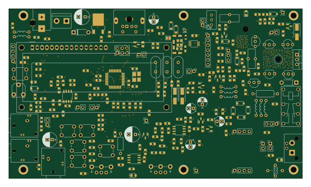
RFBitBangSMT
152 × 88 mm263 parts2LNo license221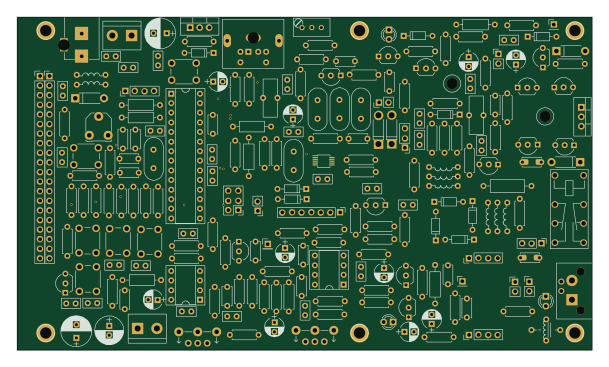 AVR/Arduino
RFBitBanger
152 × 88 mm226 parts2LNo license221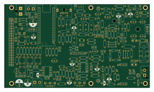 AVR/Arduino
RFBitBangerNano
152 × 88 mm209 parts2LNo license221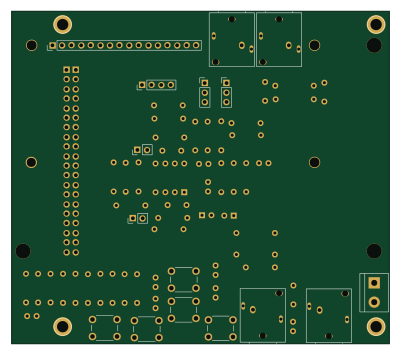
BitBangDisplay
100 × 88 mm78 parts2LNo license221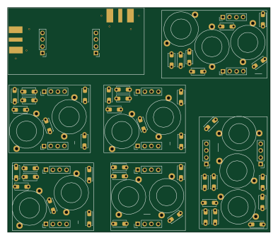
BandPassFilter
98 × 84 mm72 parts2LNo license221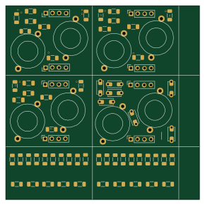
SerialResonantFilter
72.4 × 72.4 mm66 parts2LNo license221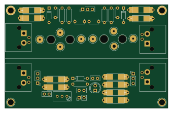
MatchTester
85 × 54 mm51 parts2LNo license221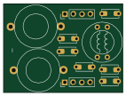
LowPassFilter
35.6 × 26.4 mm11 parts2LNo license221
Similar boards
 AVR/Arduino
Redox keyboard
mattdibi
162.2 × 126.5 mm77 parts2LMIT2.0k AVR/Arduino
ModuleV450
stuartpittaway
30 × 61.4 mm39 parts2LCC-BY-NC-4.01.1k AVR/Arduino
V4
30 × 50 mm38 parts2LCC-BY-NC-4.01.1k AVR/Arduino
Discipline
coseyfannitutti
304.9 × 122.8 mm170 parts2LCC-BY-NC-4.01.0k AVR/Arduino
Megadesk
gcormier
41.7 × 32.2 mm23 parts2LGPL-3.0818 AVR/Arduino
Easyduino Atmega Nano
Hanqaqa
43.4 × 18 mm30 parts4LCERN-OHL-P-2.0746