
PumaTX MB HW01

About the PumaTX MB HW01 PCB
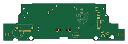
PumaTX MB HW01 is an open source RP2040/RP2350 PCB design by PumaFPV, published on GitHub under the MIT license. It is a 4-layer board measuring 130 × 40 mm, with 84 components from 46 distinct parts.
Its main chip is the ESP32-PICO-D4, from the RP2040/RP2350 family. Other key parts include the E28-2G4M27S, SX1280 and MIC5528-3.3YMT-T5. By type, the board carries 34 capacitors, 18 resistors, 9 connectors, 5 ICs, 4 jumpers and 4 inductors.
It belongs with the power & battery designs in this gallery.
From the project
DIY FPV Remote controller based on the one from the mavic
RC04: Software: PPM SBus Hall Effect Pots reading (Left pot mode switch left = down ; Right = up ; RTH = overwrite) Arm reading Pre reading RTH reading Power on / off via sport switch basic screen use + vbat + splash screen
Hardware: Micro USB (from controller) 2S LiPo external RF (R9M) USB 2.0 (or 3.0 if I find one,) to plug in module (gnd, 5v, VBat, Tx) Support for JR module in phone holder
Main components on the PumaTX MB HW01
PumaTX MB HW01 bill of materials (BOM)
84 components, 46 distinct parts — part numbers from the project's BOM.
| Qty | Part | Footprint | Refs |
|---|---|---|---|
| 1 | ESP32-PICO-D4 | ESP32-PICO-D4_1 | U400 |
| 1 | E28-2G4M27S | E28-2G4M27S | U402 |
| 1 | SX1280 | QFN50P400X400X100-25N-D | U410 |
| 2 | MIC5528-3.3YMT-T5 | SON40P120X120X60-7N-D | U520, U530 |
| 1 | Motor_DC | GL200A_HAPTIC_MOTOR | M130 |
| 1 | Fan | SM02B-SURS-TF | M140 |
| 2 | ZXMN3B01F | SOT-23 | Q130, Q140 |
| 1 | NX2016SA-52MHZ-EXS00A-CS06016 | NX2016SA32MEXS00ACS06465 | Y410 |
| 1 | PSoM_ESP32S2_Carrier_Board | PSoM_ESP32S2_00 | J1 |
| 1 | FFC2B28-12-G | GCT_FFC2B28-12-G | J2 |
| 1 | FH12A-26S-0.5SH(55) FH12A-26S-0.5SH_55_ | FH12A26S05SH55 | J100 |
| 2 | 500334-0160 | 5003340160 | J102, J103 |
| 1 | 692122030100 | 692122030100 | J104 |
| 1 | 53398-0667 | 533980667 | J105 |
| 2 | U.FL-R-SMT-1(40) U.FL-R-SMT-1_40_ | u.fl | J400, J410 |
| 1 | Buzzer | GL200A_BUZZER | BZ100 |
| 4 | Jumper_2_Small_Open | SolderJumper-2_P1.3mm_Open_RoundedPad1.0x1.5mm | JP1, JP2, JP3, JP4 |
| 2 | SKRPABE010 | SKRPABE010 | S110, S120 |
| 2 | S1GHE | S1GHE | D130, D140 |
| 1 | L | C_0402_1005Metric | L400 |
Show 26 more
| Qty | Part | Footprint | Refs |
|---|---|---|---|
| 1 | 3n | C_0402_1005Metric | L411 |
| 1 | 2N5 2n5 | C_0402_1005Metric | L412 |
| 1 | 15U 15u | C_0805_2012Metric | L414 |
| 1 | 2n2 | C_0402_1005Metric | C1 |
| 2 | 1n | C_0402_1005Metric | C2, C102 |
| 1 | 15u | C_0402_1005Metric | C3 |
| 1 | 2N2 2n2 | C_0402_1005Metric | C101 |
| 5 | 15U 15u | C_0402_1005Metric | C103, C301, C302, C303, C304 |
| 7 | 100N 100n | C_0402_1005Metric | C110, C120, C130, C140, C418, C420, C450 |
| 2 | 1u | C_0402_1005Metric | C401, C451 |
| 2 | C | C_0201_0603Metric | C406, C407 |
| 1 | 0P8 0p8 | C_0201_0603Metric | C410 |
| 2 | 1P2 1p2 | C_0201_0603Metric | C411, C412 |
| 1 | 100P 100p | C_0201_0603Metric | C413 |
| 1 | 0P5 0p5 | C_0201_0603Metric | C414 |
| 2 | 10N 10n | C_0402_1005Metric | C415, C416 |
| 1 | 470N 470n | C_0603_1608Metric | C419 |
| 1 | 10U 10u | C_0402_1005Metric | C452 |
| 4 | 2U2 2u2 | C_0603_1608Metric | C520, C521, C530, C531 |
| 2 | 4K7 4k7 | C_0402_1005Metric | R110, R120 |
| 2 | 10K 10k | C_0402_1005Metric | R130, R140 |
| 2 | 180 | C_0402_1005Metric | R131, R141 |
| 4 | 2K2 2k2 | C_0201_0603Metric | R301, R302, R303, R304 |
| 1 | 10K 10k | C_0201_0603Metric | R401 |
| 5 | 1k | C_0201_0603Metric | R410, R411, R412, R413, R414 |
| 2 | 0 | C_0201_0603Metric | R511, R512 |
PumaTX MB HW01 design files
The KiCad project lives in the PumaFPV/PumaTX repository on GitHub; these links point at the commit this page was built from.
PumaTX MB HW01: common questions
What microcontroller does the PumaTX MB HW01 use?
The PumaTX MB HW01 is built around the ESP32-PICO-D4, from the RP2040/RP2350 family.
How big is the PumaTX MB HW01 PCB?
The PumaTX MB HW01 measures 130 × 40 mm, has 4 copper layers and is 1.2204 mm thick.
How many components are on the PumaTX MB HW01?
84 components, from 46 distinct parts, with part numbers taken from the project's own BOM. The full bill of materials is listed on this page.
Where can I download the PumaTX MB HW01 design files?
From the PumaFPV/PumaTX repository on GitHub, which has the KiCad layout, the schematic and the BOM; the links under Design files point to each one.
Can I use the PumaTX MB HW01 design in my own project?
Yes, under the terms of its MIT license, which PumaFPV chose for the repository.
Can I test firmware for the PumaTX MB HW01 without the hardware?
Yes. HardLabs builds a simulation of the board from its netlist and BOM, so you can run and debug RP2040/RP2350 firmware against it before you order a PCB.
More boards in PumaTX
Similar boards
 RP2040/RP2350
Open Book Abridged Edition
joeycastillo
85 × 115 mm29 parts2LCC-BY-SA-4.08.1k RP2040/RP2350
Corne
foostan
277.2 × 107.5 mm164 parts2LCC-BY-4.07.7k RP2040/RP2350
Corne
277.2 × 107.5 mm164 parts2LCC-BY-4.07.7k RP2040/RP2350
Jitx design
gusmanb
55.5 × 65 mm26 parts4LGPL-3.05.0k RP2040/RP2350
LogicAnalyzer
57 × 55.2 mm6 parts2LGPL-3.05.0k RP2040/RP2350
Main
google
98 × 71 mm102 parts2LApache-2.02.9k