
EspToPico

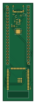
About the EspToPico PCB
EspToPico is an open source ESP32 PCB design by purduehackers, published on GitHub. It is a 2-layer board measuring 25.8 × 83.7 mm, with 15 components from 11 distinct parts.
Its main chip is the ESP32-WROOM-E, from the ESP32 family. Other key parts include the AP2112K-3.3, TPD3E001DRLR and MCP2200-I-MQ. By type, the board carries 4 ICs, 4 capacitors, 3 connectors, 2 resistors, 1 crystal and 1 diode.
It belongs with the iot & wireless designs in this gallery.
From the project
ESP to Pico form factor converter
The next revision of the board (3) should fix the following problems: - It is impossible to program the board without resorting to using the bodged boot button. The official ESP32 dev board uses the serial chip to reset the ESP32 and put it in boot mode. Schematics are available online. This would be ideal. - The button switch and LED lines had to be reversed here since the LED line was sent to an input-only pin. I reversed the labels for rev 2, but now there is a mismatch to the motherboard. This could be fixed later but it doesn't matter very much. - The EEPROM MOSI, SCK, and CS lines are…
Main components on the EspToPico
EspToPico bill of materials (BOM)
15 components, 11 distinct parts.
| Qty | Part | Footprint | Refs |
|---|---|---|---|
| 1 | ESP32-WROOM-E | ESP32-WROOM-32E | U1 |
| 1 | AP2112K-3.3 | SOT-23-5 | U2 |
| 1 | TPD3E001DRLR | SOT-553 | U3 |
| 1 | MCP2200-I-MQ | QFN-20-1EP_5x5mm_P0.65mm_EP3.35x3.35mm | U4 |
| 1 | CSTCE12M0G15L | CSTCE12M0G15L | Y1 |
| 2 | Conn_01x20_Pin | PinHeader_1x20_P2.54mm_Vertical | J1, J2 |
| 1 | USB_C_Receptacle_USB2.0_16P | USB_C_Receptacle_GCT_USB4105-xx-A_16P_TopMnt_Horizontal | J3 |
| 1 | D | D_SOD-323 | D1 |
| 2 | 0.1uF | C_0402_1005Metric | C1, C2 |
| 2 | 1uF | C_0402_1005Metric | C3, C4 |
| 2 | 5.1K | R_0402_1005Metric | R1, R2 |
EspToPico design files
The KiCad project lives in the purduehackers/EspToPico repository on GitHub; these links point at the commit this page was built from.
- LayoutEspToPico.kicad_pcb
- SchematicEspToPico.kicad_sch
EspToPico: common questions
What microcontroller does the EspToPico use?
The EspToPico is built around the ESP32-WROOM-E, from the ESP32 family.
How big is the EspToPico PCB?
The EspToPico measures 25.8 × 83.7 mm, has 2 copper layers and is 1.6 mm thick.
How many components are on the EspToPico?
15 components, from 11 distinct parts. The full bill of materials is listed on this page.
Where can I download the EspToPico design files?
From the purduehackers/EspToPico repository on GitHub, which has the KiCad layout and the schematic; the links under Design files point to each one.
Can I use the EspToPico design in my own project?
The repository has no license, so all rights stay with purduehackers. Use it as a reference, and ask the author before reusing the design.
Can I test firmware for the EspToPico without the hardware?
Yes. HardLabs builds a simulation of the board from its netlist and BOM, so you can run and debug ESP32 firmware against it before you order a PCB.
Similar boards
 ESP32
OSO-BOOK-B1
joeycastillo
85 × 115 mm65 parts2LCC-BY-SA-4.08.1k ESP32
Powertrain
byrantech
64 × 45.4 mm171 parts4LMIT4.3k ESP32
Esp32 minimal
atopile
36.2 × 26.8 mm20 parts2LMIT4.0k ESP32
Badge
56.3 × 39 mm239 parts4LMIT4.0k ESP32
Racer
StuckAtPrototype
36 × 50.2 mm70 parts4LApache-2.03.8k ESP32
Controller
29 × 74 mm58 parts4LApache-2.03.8k