
RP2040-PicoProbe

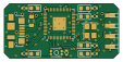
About the RP2040-PicoProbe PCB
RP2040-PicoProbe is an open source RP2040/RP2350 PCB design by red-scorp, published on GitHub. It is a 4-layer board measuring 27.9 × 13.2 mm, with 40 components from 18 distinct parts.
Its main chip is the C2040, from the RP2040/RP2350 family. Other key parts include the W25Q128JVS, C2652100, C2456297 and C37970. By type, the board carries 15 capacitors, 7 resistors, 6 ICs, 6 diodes, 3 connectors and 1 crystal.
From the project
RP2040-based minimalistic debug probe board
The RP2040-PicoProbe project aims to create even smaller version of RP2040-DebugProbe.
The RP2040-PicoProbe board is a 4-layer design intended to accommodate the popular Raspberry Pi RP2040 MCU with all required component to function identically to Raspberry Pi Debug Probe.
This board features target debug connector and PC host micro-USB connector.The board is pin-compatible with Raspberry Pi Debug Probe and can be used with the same picoprobe SW.
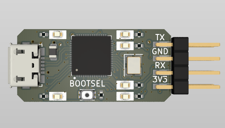
Main components on the RP2040-PicoProbe
RP2040-PicoProbe bill of materials (BOM)
40 components, 18 distinct parts — part numbers from the project's BOM.
| Qty | Part | Footprint | Refs |
|---|---|---|---|
| 1 | W25Q128JVS | SOIC-8_5.23x5.23mm_P1.27mm | U1 |
| 1 | C2040 RP2040 | QFN-56-1EP_7x7mm_P0.4mm_EP3.2x3.2mm | U2 |
| 2 | C2652100 74AUP1T17 | SOT-353_SC-70-5 | U3, U6 |
| 1 | C2456297 W25Q128JVEIQ | WSON-8-1EP_6x5mm_P1.27mm_EP3.4x4.3mm | U4 |
| 1 | C37970 MIC5205-3.3YM5 | SOT-23-5 | U5 |
| 1 | C9002 12MHz | Crystal_SMD_3225-4Pin_3.2x2.5mm | Y1 |
| 1 | CONN_UART | Harwin_M20-89004xx_1x04_P2.54mm_Horizontal | J1 |
| 1 | CONN_DBG | Harwin_M20-89004xx_1x04_P2.54mm_Horizontal | J2 |
| 1 | C2763165 USB_B_Micro | USB_Micro-B_Molex_47346-0001 | J5 |
| 1 | C913786 BOOTSEL | SW_EVPBB0AAB000 | S1 |
| 2 | C72043 GREEN | LED_0603_1608Metric | D1, D6 |
| 2 | C2286 RED | LED_0603_1608Metric | D2, D5 |
| 2 | C72038 YELLOW | LED_0603_1608Metric | D4, D7 |
| 1 | C1015 100@100MHz | L_0805_2012Metric | FB2 |
| 3 | C1604 2.2uF | C_0603_1608Metric | C1, C5, C16 |
| 10 | C1525 100nF | C_0402_1005Metric | C2, C4, C6, C8, C9, C10, C11, C13 +2 |
| 2 | C15850 10uF | C_0805_2012Metric | C14, C15 |
| 7 | C11702 1k | R_0402_1005Metric | R1, R2, R3, R4, R5, R6, R7 |
RP2040-PicoProbe design files
The KiCad project lives in the red-scorp/RP2040-PicoProbe repository on GitHub; these links point at the commit this page was built from.
RP2040-PicoProbe: common questions
What microcontroller does the RP2040-PicoProbe use?
The RP2040-PicoProbe is built around the C2040, from the RP2040/RP2350 family.
How big is the RP2040-PicoProbe PCB?
The RP2040-PicoProbe measures 27.9 × 13.2 mm, has 4 copper layers and is 1.6062 mm thick.
How many components are on the RP2040-PicoProbe?
40 components, from 18 distinct parts, with part numbers taken from the project's own BOM. The full bill of materials is listed on this page.
Where can I download the RP2040-PicoProbe design files?
From the red-scorp/RP2040-PicoProbe repository on GitHub, which has the KiCad layout, the schematic and the BOM; the links under Design files point to each one.
Can I use the RP2040-PicoProbe design in my own project?
The repository has no license, so all rights stay with red-scorp. Use it as a reference, and ask the author before reusing the design.
Can I test firmware for the RP2040-PicoProbe without the hardware?
Yes. HardLabs builds a simulation of the board from its netlist and BOM, so you can run and debug RP2040/RP2350 firmware against it before you order a PCB.
Similar boards
 RP2040/RP2350
Open Book Abridged Edition
joeycastillo
85 × 115 mm29 parts2LCC-BY-SA-4.08.1k RP2040/RP2350
Corne
foostan
277.2 × 107.5 mm164 parts2LCC-BY-4.07.7k RP2040/RP2350
Corne
277.2 × 107.5 mm164 parts2LCC-BY-4.07.7k RP2040/RP2350
Msa
Mentra-Community
47.8 × 9.4 mm53 parts2LMIT1.2k RP2040/RP2350
Open Source Smart Glasses
93 × 10.5 mm80 parts4LMIT1.2k RP2040/RP2350
MSA
30.5 × 138 mm61 parts2LMIT1.2k