
Motor controller

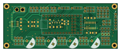
About the Motor controller PCB
Motor controller is an open source NXP PCB design by reubenstr, published on GitHub under the MIT license. It is a 4-layer board measuring 100 × 40 mm, with 63 components from 17 distinct parts.
Its main chip is the Teensy4.0, from the NXP family. Other key parts include the ACS712xLCTR-20A and ULN2003. By type, the board carries 35 connectors, 14 resistors, 6 capacitors, 3 ICs, 3 jumpers and 2 transistors.
It belongs with the robotics & motion, displays & leds and power & battery designs in this gallery.
From the project
A quadruped robot dog!
All works in progress, PCBs on the way for testing, not for production.
There are currently two paths for controlling the servos and peripherals:
1) Expansion board: RPi 4 direct connect using PWM and ADC controllers of I2C
2) Motor Controller: Teensy is responsible for PWM and ADC at the expense of complex micro-ros.
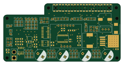
RPi expansion board to control servo motors and other peripherals without using a microcontroller.
Main components on the Motor controller
Motor controller bill of materials (BOM)
63 components, 17 distinct parts — part numbers from the project's BOM.
| Qty | Part | Footprint | Refs |
|---|---|---|---|
| 1 | ACS712xLCTR-20A | SOIC-8_3.9x4.9mm_P1.27mm | U1 |
| 1 | Teensy4.0 | Teensy40 | U2 |
| 1 | ULN2003 | SOIC-16_3.9x9.9mm_P1.27mm | U3 |
| 2 | BSS138 | SOT-23 | Q1, Q2 |
| 8 | Conn_01x04 | PinHeader_1x04_P2.54mm_Vertical | J1, J2, J5, J10, J15, J16, J17, J18 |
| 8 | Conn_01x02 | PinHeader_1x02_P2.54mm_Vertical | J3, J4, J7, J8, J9, J11, J12, J13 |
| 1 | Conn_01x02 | AMASS_XT30U-M_1x02_P5.0mm_Vertical | J6 |
| 1 | Conn_01x06 | PinHeader_1x06_P2.54mm_Vertical | J14 |
| 17 | Conn_01x03 | PinHeader_1x03_P2.54mm_Vertical | J19, J20, J21, J22, J23, J24, J25, J26 +9 |
| 3 | Jumper_3_Open | PinHeader_1x03_P2.54mm_Vertical | JP1, JP2, JP3 |
| 1 | 1nF | C_1206_3216Metric_Pad1.33x1.80mm_HandSolder | C1 |
| 1 | 100nF | C_1206_3216Metric_Pad1.33x1.80mm_HandSolder | C2 |
| 4 | 2200uF | CP_Radial_D10.0mm_P5.00mm | C3, C4, C5, C6 |
| 4 | 1.2k | R_1206_3216Metric_Pad1.30x1.75mm_HandSolder | R1, R3, R8, R10 |
| 6 | 10k | R_1206_3216Metric_Pad1.30x1.75mm_HandSolder | R2, R4, R5, R6, R7, R11 |
| 2 | 20k | R_1206_3216Metric_Pad1.30x1.75mm_HandSolder | R9, R12 |
| 2 | 500Ω | R_1206_3216Metric_Pad1.30x1.75mm_HandSolder | R13, R14 |
Motor controller design files
The KiCad project lives in the reubenstr/zuko repository on GitHub; these links point at the commit this page was built from.
Motor controller: common questions
What microcontroller does the Motor controller use?
The Motor controller is built around the Teensy4.0, from the NXP family.
How big is the Motor controller PCB?
The Motor controller measures 100 × 40 mm, has 4 copper layers and is 1.6 mm thick.
How many components are on the Motor controller?
63 components, from 17 distinct parts, with part numbers taken from the project's own BOM. The full bill of materials is listed on this page.
Where can I download the Motor controller design files?
From the reubenstr/zuko repository on GitHub, which has the KiCad layout, the schematic and the BOM; the links under Design files point to each one.
Can I use the Motor controller design in my own project?
Yes, under the terms of its MIT license, which reubenstr chose for the repository.
Can I test firmware for the Motor controller without the hardware?
Yes. HardLabs builds a simulation of the board from its netlist and BOM, so you can run and debug NXP firmware against it before you order a PCB.
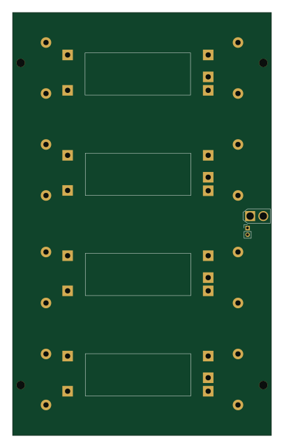
More boards in zuko
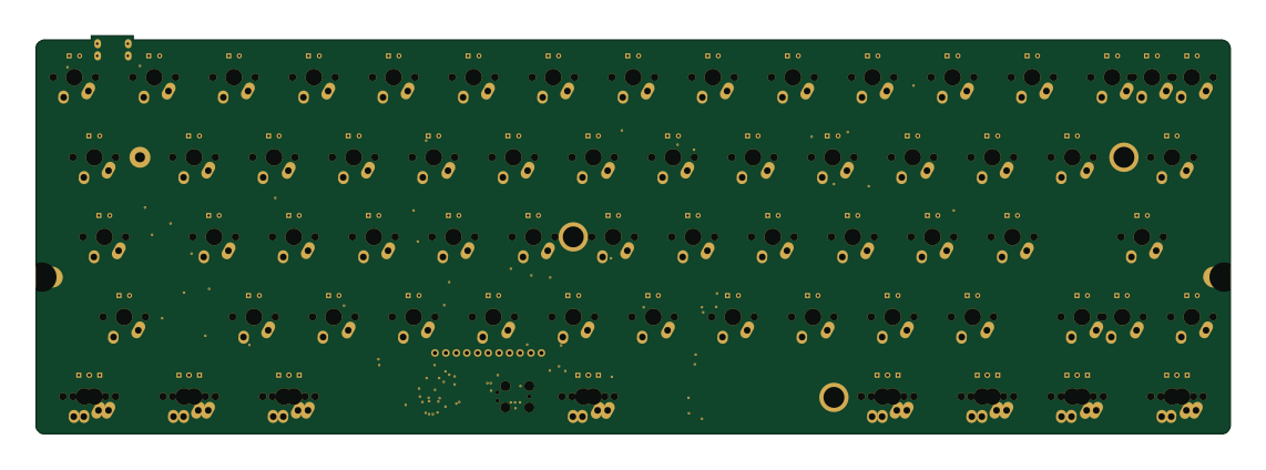
Similar boards
 NXP
NXPIC60
kiibohd
285 × 95 mm242 partsCERN-OHL-1.2415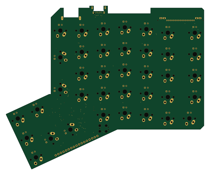 NXP
NXPICED-R
175.4 × 145 mm163 partsCERN-OHL-1.2415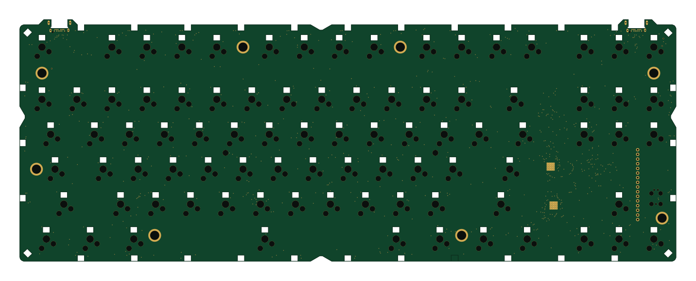 NXP
NXPK-Type
357.5 × 131.8 mm361 partsCERN-OHL-1.2415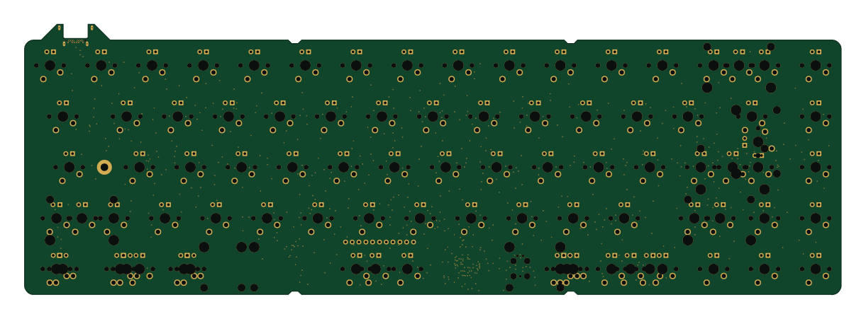 NXP
NXPWhiteFox
304.8 × 101.1 mm296 partsCERN-OHL-1.2415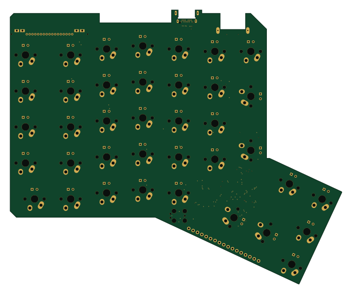 NXP
NXPICED-L
175.4 × 145 mm163 partsCERN-OHL-1.2415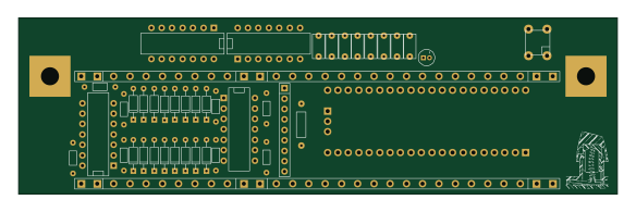 NXP
NXPTestcontroller
145.8 × 42.9 mm45 parts2LCERN-OHL-1.2415