
TTGO-T1-Booster

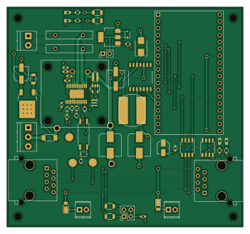
About the TTGO-T1-Booster PCB
TTGO-T1-Booster is an open source PCB design by RobertPHeller, published on GitHub under the CC-BY-4.0 license. It is a 2-layer board measuring 87.6 × 81.5 mm, with 62 components from 48 distinct parts.
Other key parts include the INA180B, TTGO-T1, LM358, TCAN332DR and LM2574N-5.0. By type, the board carries 15 capacitors, 15 resistors, 10 diodes, 9 ICs, 5 connectors and 2 fuses.
From the project
Command Stations and Boosters
This is a collection of LCC/DCC Command Stations and Boosters. The Command Stations are Beagle Board based, leveraging the PRUs in the TI AM335x processors to generate the DCC signals accuratly without worrying about Linux kernel premption or needing a real-time kernel module. The compainion booster is ESP32 based.
Main components on the TTGO-T1-Booster
TTGO-T1-Booster bill of materials (BOM)
62 components, 48 distinct parts.
| Qty | Part | Footprint | Refs |
|---|---|---|---|
| 1 | INA180B | SOT-23-5 | U101 |
| 1 | TTGO-T1 | TIGO-T1 | U201 |
| 1 | LM358 | SOIC-8_3.9x4.9mm_Pitch1.27mm | U301 |
| 1 | TCAN332DR | SOIC-8_3.9x4.9mm_Pitch1.27mm | U302 |
| 1 | LM2574N-5.0 | SOIC-14_7.4x8.7mm_Pitch1.27mm | U401 |
| 1 | LF120_TO220 | TO-252-2 | U402 |
| 1 | MCP9700T-E_LT | SOT65P210X110-5N | U501 |
| 1 | VO615A | SO-4_7.6x3.6mm_Pitch2.54mm | U601 |
| 1 | DRV8873HPWPR | SOP65P640X120-25N | U602 |
| 1 | Fan_IEC60617 | 25mmFanMount | M501 |
| 1 | BSP52T3G | SOT-223 | Q501 |
| 1 | - Power + in - | TerminalBlock_Pheonix_PT-3.5mm_3pol | J101 |
| 1 | Output to tracks | TerminalBlock_Pheonix_PT-3.5mm_2pol | J102 |
| 2 | RJ45 | RJ45_8N-S | J301, J302 |
| 1 | - Fan + | Pin_Header_Straight_1x02_Pitch2.54mm | J501 |
| 2 | 5A | MFR500 | F101, F102 |
| 1 | Termination | Pin_Header_Straight_2x02_Pitch2.54mm | JP301 |
| 1 | - 15 in + | TerminalBlock_Pheonix_MPT-2.54mm_2pol | T301 |
| 1 | - 15 out + | TerminalBlock_Pheonix_MPT-2.54mm_2pol | T302 |
| 1 | RB080LAM-30TR | PMDTM | D101 |
Show 28 more
| Qty | Part | Footprint | Refs |
|---|---|---|---|
| 1 | OPS ActB | LED_0603 | D102 |
| 1 | OPS ActA | LED_0603 | D103 |
| 1 | Tx | LED_0603 | D301 |
| 1 | Rx | LED_0603 | D302 |
| 2 | DFLS240-7 | D_PowerDI-123 | D303, D304 |
| 1 | CMSH1-60 TR13 | D_SMB | D401 |
| 1 | 1SS352H3F | D_SOD-323 | D501 |
| 1 | 1.5v 10ma | D_SOD-323 | D601 |
| 1 | 330 uh | SRN1060 | L401 |
| 2 | 10 nf | C_1206 | C101, C403 |
| 1 | .1 uf | C_0603 | C301 |
| 1 | 15 uf 15V | CP_Elec_4x5.7 | C302 |
| 2 | 47 nf | C_0603 | C303, C602 |
| 1 | 220 uf 25V | CP_Elec_8x10 | C401 |
| 1 | 22 uf 100V | CP_Elec_8x10 | C402 |
| 1 | 10 uf | CP_Elec_5x5.3 | C404 |
| 1 | 100 uf | C_0603 | C501 |
| 2 | 1 uf | C_0603 | C601, C603 |
| 2 | 100 nf | C_0603 | C604, C605 |
| 1 | 47 uf | CP_Elec_6.3x5.3 | C606 |
| 1 | 2.4 | R_1206 | R101 |
| 2 | 3K | R_0603 | R102, R103 |
| 2 | 160 | R_0603 | R301, R302 |
| 2 | 60 Ohms | R_1206 | R303, R304 |
| 1 | 1K | R_0603 | R501 |
| 1 | 2.2K | R_0603 | R601 |
| 5 | 10K | R_0603 | R602, R603, R604, R605, R606 |
| 1 | 0.005 1% | R_0612 | R607 |
TTGO-T1-Booster design files
The KiCad project lives in the RobertPHeller/CommandStationsAndBoosters repository on GitHub; these links point at the commit this page was built from.
TTGO-T1-Booster: common questions
How big is the TTGO-T1-Booster PCB?
The TTGO-T1-Booster measures 87.6 × 81.5 mm, has 2 copper layers and is 1.6 mm thick.
How many components are on the TTGO-T1-Booster?
62 components, from 48 distinct parts. The full bill of materials is listed on this page.
Where can I download the TTGO-T1-Booster design files?
From the RobertPHeller/CommandStationsAndBoosters repository on GitHub, which has the KiCad layout; the links under Design files point to each one.
Can I use the TTGO-T1-Booster design in my own project?
Yes, under the terms of its CC-BY-4.0 license, which RobertPHeller chose for the repository.
More boards in CommandStationsAndBoosters
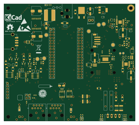
PocketBeagleCommandStation SMD
118.1 × 105.4 mm131 parts4LCC-BY-4.00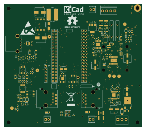
PocketBeagleCommandStation SMD RevB 2L
118.1 × 105.4 mm128 parts2LCC-BY-4.00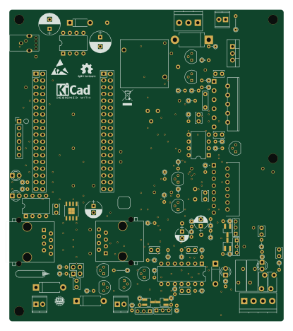
PocketBeagleCommandStation
102.9 × 116.7 mm112 parts2LCC-BY-4.00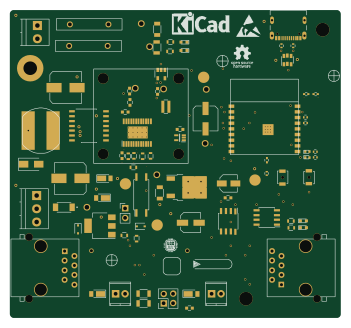 ESP32
ESP32ESP32-C3-Booster
87.6 × 81.5 mm80 parts2LCC-BY-4.00
BBBCommandStation
39.4 × 108 mm68 parts2LCC-BY-4.00
PBCommandStation
99.1 × 109.2 mm50 parts2LCC-BY-4.00