
ESP32-C3-Booster

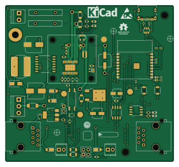
About the ESP32-C3-Booster PCB
ESP32-C3-Booster is an open source ESP32 PCB design by RobertPHeller, published on GitHub under the CC-BY-4.0 license. It is a 2-layer board measuring 87.6 × 81.5 mm, with 80 components from 58 distinct parts.
Its main chip is the ESP32-C3-WROOM, from the ESP32 family. Other key parts include the USBLC6-2SC6, INA180B, LM358, TCAN332DR and LM2574HVM-3.3. By type, the board carries 22 resistors, 18 capacitors, 14 diodes, 10 ICs, 7 connectors and 2 fuses.
From the project
Command Stations and Boosters
ESP32 C3 based DCC Booster. This booster should work with any LCC command station that puts the DCC Signal out on pins 4 and 5 ("Alt") of the LCC network bus.
Mouser Cart Schematic PDF Board Rendering Node Firmware
Main components on the ESP32-C3-Booster
ESP32-C3-Booster bill of materials (BOM)
80 components, 58 distinct parts.
| Qty | Part | Footprint | Refs |
|---|---|---|---|
| 1 | ESP32-C3-WROOM | ESP32-C3-WROOM | IC201 |
| 1 | USBLC6-2SC6 | SOT-23-6 | IC202 |
| 1 | INA180B | SOT-23-5 | U101 |
| 1 | LM358 | SOIC-8_3.9x4.9mm_Pitch1.27mm | U301 |
| 1 | TCAN332DR | SOIC-8_3.9x4.9mm_Pitch1.27mm | U302 |
| 1 | LM2574HVM-3.3 | SOIC-14_7.4x8.7mm_Pitch1.27mm | U401 |
| 1 | LF120_TO220 | TO-252-2 | U402 |
| 1 | DRV8873HPWPR | SOP65P640X120-25N | U501 |
| 1 | VO615A | SO-4_7.6x3.6mm_Pitch2.54mm | U502 |
| 1 | MCP9700T-E_LT | SOT65P210X110-5N | U601 |
| 1 | Fan_IEC60617 | 25mmFanMount | M601 |
| 1 | BSP52T3G | SOT-223 | Q601 |
| 1 | - Power + In - | TerminalBlock_Pheonix_PT-3.5mm_3pol | J101 |
| 1 | Output to tracks | TerminalBlock_Pheonix_PT-3.5mm_2pol | J102 |
| 1 | USB_C | GCT_USB4105-GF-A | J201 |
| 1 | Termination | Pin_Header_Straight_2x02_Pitch2.54mm | J301 |
| 2 | RJ45 | RJ45_8N-S | J302, J303 |
| 1 | - Fan + | Pin_Header_Straight_1x02_Pitch2.54mm | J601 |
| 2 | 5A | MFR500 | F101, F102 |
| 1 | RESET | SW_SPST_B3U-1000P-B | SW201 |
Show 38 more
| Qty | Part | Footprint | Refs |
|---|---|---|---|
| 1 | BOOT | SW_SPST_B3U-1000P-B | SW202 |
| 1 | LCC Power Out | TerminalBlock_Pheonix_MPT-2.54mm_2pol | T301 |
| 1 | LCC Power In | TerminalBlock_Pheonix_MPT-2.54mm_2pol | T302 |
| 1 | RB080LAM-30TR | PMDTM | D101 |
| 1 | OPS ActB | LED_0603 | D102 |
| 1 | OPS ActA | LED_0603 | D103 |
| 1 | ACT1 | LED_0402 | D201 |
| 1 | ACT2 | LED_0402 | D202 |
| 1 | Tx | LED_0603 | D301 |
| 1 | Rx | LED_0603 | D302 |
| 4 | DFLS240 | D_PowerDI-123 | D303, D304, D402, D403 |
| 1 | CMSH1-60 | D_SMA | D401 |
| 1 | 1.5v 10ma | D_SOD-323 | D501 |
| 1 | 1SS352H3F | D_SOD-323 | D601 |
| 1 | 330 mh | SRN1060 | L401 |
| 2 | 10 nf | C_1206 | C101, C405 |
| 2 | 22pf | C_0402 | C201, C202 |
| 1 | 1uf | C_0402 | C210 |
| 3 | 100 nf | C_0603 | C301, C504, C505 |
| 2 | 47 nf | C_0603 | C302, C502 |
| 1 | 15 uf 15V | CP_Elec_4x5.8 | C303 |
| 1 | 220 uf 25V | CP_Elec_8x10 | C401 |
| 1 | 22 uf 100V | CP_Elec_8x10 | C403 |
| 1 | 10 uf | CP_Elec_5x5.3 | C406 |
| 2 | 1 uf | C_0603 | C501, C503 |
| 1 | 47 uf | CP_Elec_6.3x5.3 | C506 |
| 1 | 100 uf | C_0603 | C601 |
| 2 | 3K | R_0603 | R101, R103 |
| 1 | 2.4 | R_1206 | R102 |
| 3 | 10K | R_0402 | R201, R202, R203 |
| 2 | 5.1K | R_0402 | R204, R207 |
| 2 | 270 | R_0402 | R205, R206 |
| 2 | 160 | R_0603 | R301, R302 |
| 2 | 60 | R_1206 | R303, R304 |
| 5 | 10K | R_0603 | R501, R502, R503, R506, R507 |
| 1 | 0.005 1% | R_0612 | R504 |
| 1 | 2.2K | R_0603 | R505 |
| 1 | 1K | R_0603 | R601 |
ESP32-C3-Booster design files
The KiCad project lives in the RobertPHeller/CommandStationsAndBoosters repository on GitHub; these links point at the commit this page was built from.
ESP32-C3-Booster: common questions
What microcontroller does the ESP32-C3-Booster use?
The ESP32-C3-Booster is built around the ESP32-C3-WROOM, from the ESP32 family.
How big is the ESP32-C3-Booster PCB?
The ESP32-C3-Booster measures 87.6 × 81.5 mm, has 2 copper layers and is 1.6 mm thick.
How many components are on the ESP32-C3-Booster?
80 components, from 58 distinct parts. The full bill of materials is listed on this page.
Where can I download the ESP32-C3-Booster design files?
From the RobertPHeller/CommandStationsAndBoosters repository on GitHub, which has the KiCad layout; the links under Design files point to each one.
Can I use the ESP32-C3-Booster design in my own project?
Yes, under the terms of its CC-BY-4.0 license, which RobertPHeller chose for the repository.
Can I test firmware for the ESP32-C3-Booster without the hardware?
Yes. HardLabs builds a simulation of the board from its netlist and BOM, so you can run and debug ESP32 firmware against it before you order a PCB.
More boards in CommandStationsAndBoosters
PocketBeagleCommandStation SMD
118.1 × 105.4 mm131 parts4LCC-BY-4.00
PocketBeagleCommandStation SMD RevB 2L
118.1 × 105.4 mm128 parts2LCC-BY-4.00
PocketBeagleCommandStation
102.9 × 116.7 mm112 parts2LCC-BY-4.00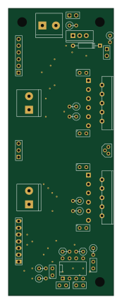
BBBCommandStation
39.4 × 108 mm68 parts2LCC-BY-4.00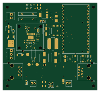
TTGO-T1-Booster
87.6 × 81.5 mm62 parts2LCC-BY-4.00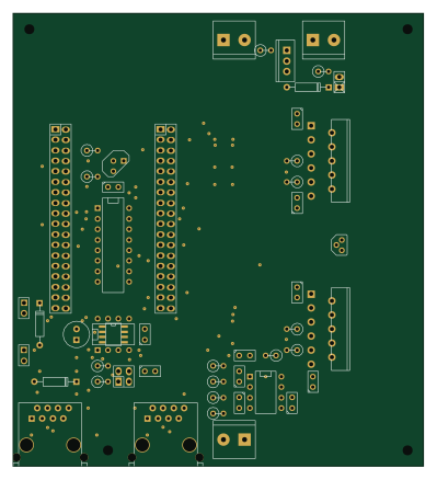
PBCommandStation
99.1 × 109.2 mm50 parts2LCC-BY-4.00
Similar boards
 ESP32
ESP32Open Book Abridged Edition
joeycastillo
85 × 115 mm65 parts2LCC-BY-SA-4.08.1k ESP32
ESP32Badge
atopile
56.3 × 39 mm239 parts4LMIT4.0k ESP32
ESP32Esp32 minimal
36.2 × 26.8 mm20 parts2LMIT4.0k ESP32
ESP32Racer
StuckAtPrototype
36 × 50.2 mm70 parts4LApache-2.03.8k ESP32
ESP32Controller
29 × 74 mm58 parts4LApache-2.03.8k ESP32
ESP32Bitaxe
skot
56.5 × 99.8 mm86 parts4LCERN-OHL-S-2.01.4k