
Astronaut lamp

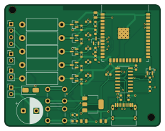
About the Astronaut lamp PCB
Astronaut lamp is an open source ESP32 PCB design by rudnik275, published on GitHub. It is a 2-layer board measuring 60 × 47 mm, with 44 components from 23 distinct parts.
Its main chip is the ESP32-WROOM-32E, from the ESP32 family. Other key parts include the CH340C and AMS1117-3.3. By type, the board carries 8 capacitors, 7 transistors, 7 resistors, 5 connectors, 3 ICs and 2 switches.
From the project
Ночник «космонавт на луне» → нативное HomeKit-устройство на ESP32 + HAA: разбор родной платы, схема драйвера, конфиг, корпус
ESP32-WROOM-32E прямо на плате, USB-C для питания и прошивки, пять ключей (R, G, B, мотор, лазер), посадочные места под выводные балласты 2 Вт и электролит 1000 µF. Плата 60 × 47 мм, двухслойная, антенна модуля свисает за верхний край на 3 мм. Проект KiCad 10 генерируется скриптами из одного описания (design.py): и схема, и плата рождаются из одного списка цепей, и их совпадение проверяется автоматически.
Main components on the Astronaut lamp
Astronaut lamp bill of materials (BOM)
44 components, 23 distinct parts — part numbers from the project's BOM.
| Qty | Part | Footprint | Refs |
|---|---|---|---|
| 1 | ESP32-WROOM-32E | ESP32-WROOM-32_body | U1 |
| 1 | CH340C | SOIC-16_3.9x9.9mm_P1.27mm | U2 |
| 1 | AMS1117-3.3 | SOT-223-3_TabPin2 | U3 |
| 5 | AO3400A | SOT-23 | Q1, Q2, Q3, Q4, Q5 |
| 2 | S8050 | SOT-23 | Q6, Q7 |
| 1 | C165948 USB-C 16p | USB_C_Receptacle_HRO_TYPE-C-31-M-12 | J1 |
| 1 | LED V G R B | PinHeader_1x04_P2.54mm_Vertical | J2 |
| 1 | MOTOR | PinHeader_1x02_P2.54mm_Vertical | J3 |
| 1 | LASER | PinHeader_1x02_P2.54mm_Vertical | J4 |
| 1 | 5V IN | PinHeader_1x02_P2.54mm_Vertical | J5 |
| 5 | 220R | R_0603_1608Metric | RG1, RG2, RG3, RG4, RG5 |
| 5 | 10K 10k | R_0603_1608Metric | RP1, RP2, RP3, RP4, RP5 |
| 1 | EN | SW_PUSH_6mm | SW1 |
| 1 | BOOT | SW_PUSH_6mm | SW2 |
| 1 | SS14 | D_SMA | D1 |
| 1 | C2286 LED red | LED_0603_1608Metric | D2 |
| 1 | 1000uF/16V | CP_Radial_D10.0mm_P5.00mm | C1 |
| 3 | 10UF 10uF | C_0805_2012Metric | C2, C3, C4 |
| 3 | 100NF 100nF | C_0603_1608Metric | C5, C7, C8 |
| 1 | 1UF 1uF | C_0603_1608Metric | C6 |
Show 3 more
| Qty | Part | Footprint | Refs |
|---|---|---|---|
| 2 | 5.1K 5.1k | R_0603_1608Metric | R1, R2 |
| 4 | 10K 10k | R_0603_1608Metric | R3, R4, R5, R6 |
| 1 | 1k | R_0603_1608Metric | R7 |
Astronaut lamp design files
The KiCad project lives in the rudnik275/astronaut-lamp repository on GitHub; these links point at the commit this page was built from.
Astronaut lamp: common questions
What microcontroller does the Astronaut lamp use?
The Astronaut lamp is built around the ESP32-WROOM-32E, from the ESP32 family.
How big is the Astronaut lamp PCB?
The Astronaut lamp measures 60 × 47 mm, has 2 copper layers and is 1.6 mm thick.
How many components are on the Astronaut lamp?
44 components, from 23 distinct parts, with part numbers taken from the project's own BOM. The full bill of materials is listed on this page.
Where can I download the Astronaut lamp design files?
From the rudnik275/astronaut-lamp repository on GitHub, which has the KiCad layout, the schematic and the BOM; the links under Design files point to each one.
Can I use the Astronaut lamp design in my own project?
The repository has no license, so all rights stay with rudnik275. Use it as a reference, and ask the author before reusing the design.
Can I test firmware for the Astronaut lamp without the hardware?
Yes. HardLabs builds a simulation of the board from its netlist and BOM, so you can run and debug ESP32 firmware against it before you order a PCB.
Similar boards
 ESP32
ESP32Open Book Abridged Edition
joeycastillo
85 × 115 mm65 parts2LCC-BY-SA-4.08.1k ESP32
ESP32Powertrain
byrantech
64 × 45.4 mm171 parts4LMIT4.3k ESP32
ESP32Badge
atopile
56.3 × 39 mm239 parts4LMIT4.0k ESP32
ESP32Esp32 minimal
36.2 × 26.8 mm20 parts2LMIT4.0k ESP32
ESP32Controller
StuckAtPrototype
29 × 74 mm58 parts4LApache-2.03.8k ESP32
ESP32Racer
36 × 50.2 mm70 parts4LApache-2.03.8k