
ME7 ECU

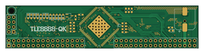
About the ME7 ECU PCB
ME7 ECU is an open source PCB design by rusefi, published on GitHub. It is a 2-layer board measuring 100 × 22 mm, with 68 components from 39 distinct parts.
Other key parts include the TS5A3166DCKR. By type, the board carries 32 resistors, 16 capacitors, 15 diodes, 3 connectors, 1 IC and 1 transistor.
From the project
*DEPRECATED* rusEFI prototyping hardware
iBom https://rusefi.com/docs/ibom/TLE8888Modulelatest.html
vdd input: logic level voltage from MCU used as reference to SPI etc communication
Open collector hall configurations: DNP=R9=R15=R16=C12=C15. R17=2.7K R12=10K R13=0R R18=2.7K R19=2.7K
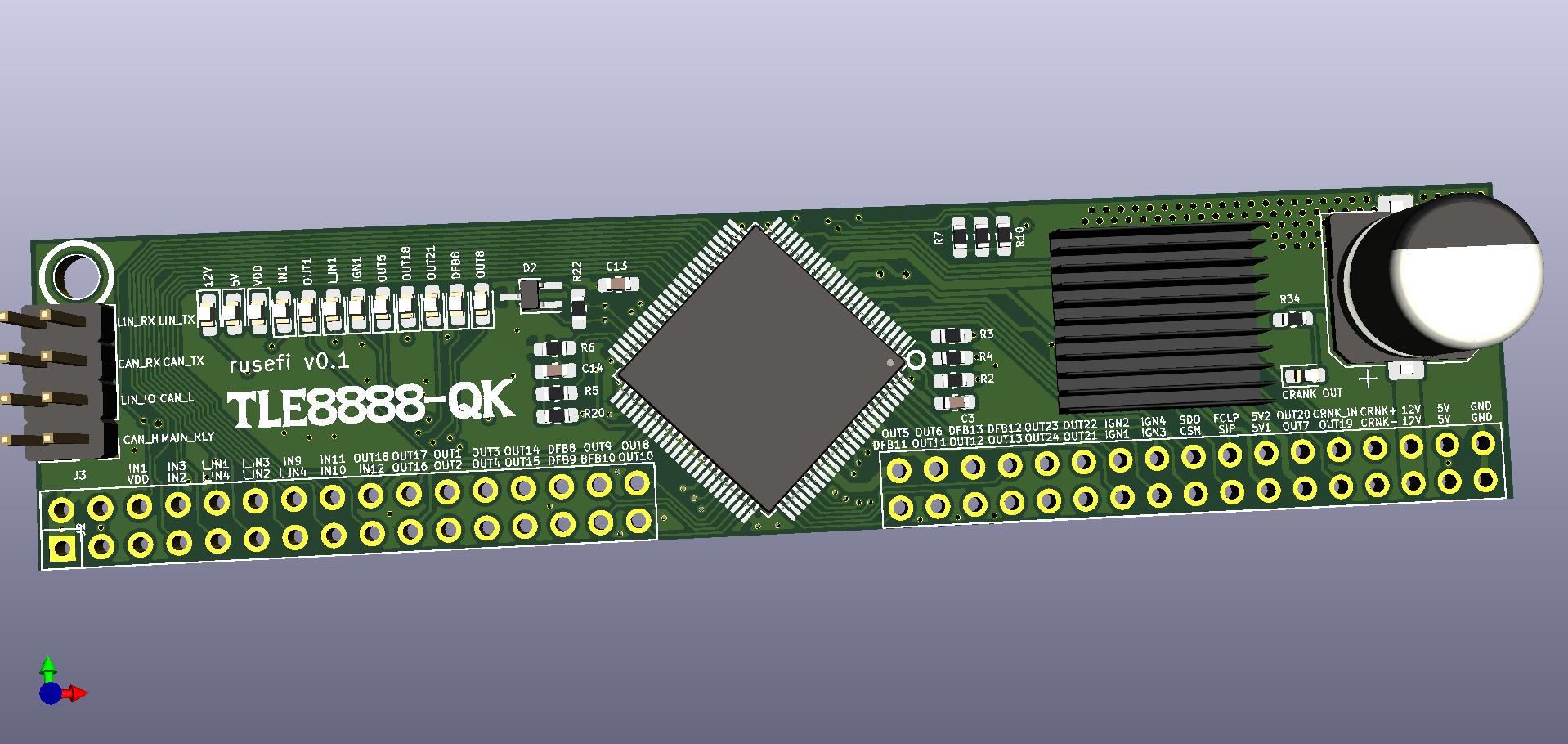
Main components on the ME7 ECU
ME7 ECU bill of materials (BOM)
68 components, 39 distinct parts — part numbers from the project's BOM.
| Qty | Part | Footprint | Refs |
|---|---|---|---|
| 1 | TS5A3166DCKR TLE8888QK | LQFP-100_14x14mm_P0.5mm_THERMAL | U2 |
| 1 | 512-RFD16N05LSM9A IPD30N06S2L-23 | TO-252-2 | Q1 |
| 1 | CONN_02X20_ODD_EVEN DNP CORNER HOLE | 1pin | J1 |
| 1 | Conn_02x39_Odd_Even | Conn_TLE8888_Module | J2 |
| 1 | Conn_02x04_Odd_Even | PinHeader_2x04_P2.54mm_Vertical | J3 |
| 1 | MBRS3200T3G | D_SMB | D1 |
| 1 | PESD1CAN-UX | SOT-323_SC-70_Handsoldering | D2 |
| 13 | LED | LED_0603_1608Metric_Pad1.05x0.95mm_HandSolder | D3, D4, D5, D7, D8, D9, D10, D11 +5 |
| 1 | C1530 100nF | C_0603_1608Metric_Pad1.05x0.95mm_HandSolder | C1 |
| 1 | C1525 100UF 50V | CP_Elec_10x10.5 | C2 |
| 1 | C1585 4.7nF | C_0603_1608Metric_Pad1.05x0.95mm_HandSolder | C3 |
| 1 | C1585 100nF | C_0603_1608Metric_Pad1.05x0.95mm_HandSolder | C4 |
| 1 | C1523 100nF | C_0603_1608Metric_Pad1.05x0.95mm_HandSolder | C5 |
| 1 | C1525 100nF | C_0603_1608Metric_Pad1.05x0.95mm_HandSolder | C6 |
| 2 | C1585 10uF | C_0603_1608Metric_Pad1.05x0.95mm_HandSolder | C7, C8 |
| 1 | 10uF | C_0603_1608Metric_Pad1.05x0.95mm_HandSolder | C9 |
| 4 | 100nF | C_0603_1608Metric_Pad1.05x0.95mm_HandSolder | C10, C13, C14, C16 |
| 1 | 4.7nF | C_0603_1608Metric_Pad1.05x0.95mm_HandSolder | C11 |
| 2 | DNP | C_0603_1608Metric_Pad1.05x0.95mm_HandSolder | C12, C15 |
| 1 | 10K 1K | R_0603_1608Metric_Pad1.05x0.95mm_HandSolder | R1 |
Show 19 more
| Qty | Part | Footprint | Refs |
|---|---|---|---|
| 1 | C22962 4.7K | R_0603_1608Metric_Pad1.05x0.95mm_HandSolder | R2 |
| 1 | 82.5R 4.7K | R_0603_1608Metric_Pad1.05x0.95mm_HandSolder | R3 |
| 1 | C25741 4.7K | R_0603_1608Metric_Pad1.05x0.95mm_HandSolder | R4 |
| 1 | C25790 0 | R_0603_1608Metric_Pad1.05x0.95mm_HandSolder | R5 |
| 1 | C22962 0 | R_0603_1608Metric_Pad1.05x0.95mm_HandSolder | R6 |
| 1 | 10K 0 | R_0603_1608Metric_Pad1.05x0.95mm_HandSolder | R7 |
| 1 | C25900 4.7K | R_0603_1608Metric_Pad1.05x0.95mm_HandSolder | R8 |
| 1 | C17778 DNP | R_0603_1608Metric_Pad1.05x0.95mm_HandSolder | R9 |
| 1 | C25917 4.7K | R_0603_1608Metric_Pad1.05x0.95mm_HandSolder | R10 |
| 1 | C25744 1K | R_0603_1608Metric_Pad1.05x0.95mm_HandSolder | R11 |
| 2 | C25741 DNP | R_0603_1608Metric_Pad1.05x0.95mm_HandSolder | R12, R15 |
| 3 | C25744 DNP | R_0603_1608Metric_Pad1.05x0.95mm_HandSolder | R13, R17, R18 |
| 1 | C11702 1K | R_0603_1608Metric_Pad1.05x0.95mm_HandSolder | R14 |
| 1 | C11702 DNP | R_0603_1608Metric_Pad1.05x0.95mm_HandSolder | R16 |
| 1 | C25917 DNP | R_0603_1608Metric_Pad1.05x0.95mm_HandSolder | R19 |
| 1 | C25900 2.7K | R_0603_1608Metric_Pad1.05x0.95mm_HandSolder | R20 |
| 1 | C11702 2.7K | R_0603_1608Metric_Pad1.05x0.95mm_HandSolder | R21 |
| 1 | 120R | R_0603_1608Metric_Pad1.05x0.95mm_HandSolder | R22 |
| 10 | 1K | R_0603_1608Metric_Pad1.05x0.95mm_HandSolder | R24, R25, R26, R27, R28, R30, R31, R32 +2 |
ME7 ECU design files
The KiCad project lives in the rusefi/hw_modular repository on GitHub; these links point at the commit this page was built from.
ME7 ECU: common questions
How big is the ME7 ECU PCB?
The ME7 ECU measures 100 × 22 mm, has 2 copper layers and is 1.6 mm thick.
How many components are on the ME7 ECU?
68 components, from 39 distinct parts, with part numbers taken from the project's own BOM. The full bill of materials is listed on this page.
Where can I download the ME7 ECU design files?
From the rusefi/hw_modular repository on GitHub, which has the KiCad layout and the BOM; the links under Design files point to each one.
Can I use the ME7 ECU design in my own project?
The repository has no license, so all rights stay with rusefi. Use it as a reference, and ask the author before reusing the design.
More boards in hw_modular
Analog Input Module
81 × 22 mm111 parts2LNo license13
Lowside
101 × 22 mm96 parts4LNo license13
Wideband Module
45.4 × 22 mm38 parts2LNo license13
High or low side drive board for RUSEFI.com
43.4 × 20.3 mm30 parts2LNo license13
Test board 48
100 × 100 mm18 parts2LNo license13
TLE7209-2R Module
43 × 22 mm13 parts2LNo license13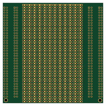
Nucleo144 wing
100 × 100 mm12 parts2LNo license13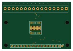
TLE8110ED low side driver chip
59.1 × 40.6 mm3 parts2LNo license13