
Stim

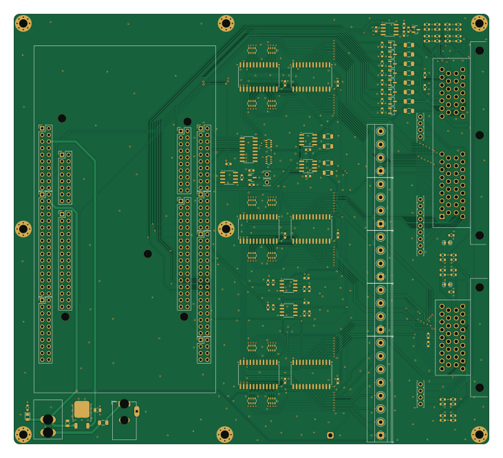
About the Stim PCB
Stim is an open source PCB design by rusefi, published on GitHub. It is a 2-layer board measuring 182.5 × 165 mm, with 169 components from 51 distinct parts.
Other key parts include the OPA4192IPW, CD4067BM96, TC4427, ULN2003A and NUCLEO-F429ZI. By type, the board carries 75 resistors, 39 connectors, 18 capacitors, 14 ICs, 9 fuses and 8 transistors.
From the project
12v DC power required one microUSB cable required for operation * sometimes second microUSB is useful for firmware update
12v DC power required one microUSB cable required for operation * sometimes second microUSB is useful for firmware update
Download Putty bottom microUSB is required for operation top microUSB is sometimes needed for firmware updates blinking blue LD2 means "alive" red LD3 means "board has failed test green LD1 next to blinking blue means "test successful"
See https://github.com/rusefi/rusefi-hardware/tree/main/digital-inputs for firmware
Main components on the Stim
Stim bill of materials (BOM)
169 components, 51 distinct parts — part numbers from the project's BOM.
| Qty | Part | Footprint | Refs |
|---|---|---|---|
| 1 | OPA4192IPW OPA2192IDR | SO-8_3.9x4.9mm_P1.27mm | U1 |
| 6 | CD4067BM96 | SOIC-24W_7.5x15.4mm_P1.27mm | U2, U3, U4, U5, U6, U7 |
| 2 | TC4427 | SOIC-8_3.9x4.9mm_P1.27mm | U8, U9 |
| 1 | ULN2003A | SOIC-16_3.9x9.9mm_P1.27mm | U10 |
| 1 | NUCLEO-F429ZI OPA2192IDR | SO-8_3.9x4.9mm_P1.27mm | U11 |
| 2 | TJA1051T-3 | SOIC-8_3.9x4.9mm_P1.27mm | U12, U13 |
| 1 | LM78M05_TO252 | TO-252-2 | U14 |
| 8 | AO3400A | SOT-23 | Q1, Q2, Q3, Q4, Q5, Q6, Q7, Q8 |
| 1 | CONN_01X16 6437288-2 | 6437288-2 | J1 |
| 1 | CONN_01X16 Barrel_Jack_Switch | BarrelJack_GCT_DCJ200-10-A_Horizontal | J2 |
| 1 | CONN_01X16 Conn_01x08 | TerminalBlock_Phoenix_MKDS-1,5-8-5.08_1x08_P5.08mm_Horizontal | J3 |
| 1 | CONN_01X01 Conn_01x01 | SolderWire-0.75sqmm_1x01_D1.25mm_OD2.3mm | J4 |
| 4 | CONN_01X04 Conn_01x04 | TerminalBlock_Phoenix_MKDS-1,5-4-5.08_1x04_P5.08mm_Horizontal | J6, J7, J8, J9 |
| 1 | 6437288-3 | TE_6437288-3 | J19 |
| 4 | Conn_02x10_Odd_Even | PinHeader_2x10_P2.54mm_Vertical | J20, J23, J25, J29 |
| 1 | Conn_02x08_Odd_Even | PinHeader_2x08_P2.54mm_Vertical | J21 |
| 1 | Conn_02x15_Odd_Even | PinHeader_2x15_P2.54mm_Vertical | J22 |
| 1 | Conn_02x17_Odd_Even | PinHeader_2x17_P2.54mm_Vertical | J24 |
| 1 | Conn_02x06_Odd_Even | PinHeader_2x06_P2.54mm_Vertical | J26 |
| 1 | Conn_02x16_Odd_Even | PinHeader_2x16_P2.54mm_Vertical | J27 |
Show 31 more
| Qty | Part | Footprint | Refs |
|---|---|---|---|
| 1 | Conn_02x04_Odd_Even | PinHeader_2x04_P2.54mm_Vertical | J28 |
| 1 | Conn_02x14_Odd_Even | PinHeader_2x16_P2.54mm_Vertical | J30 |
| 19 | Pad | PAD-TH | P1, P2, P3, P4, P5, P6, P7, P8 +11 |
| 1 | CircuitBreaker_1P | RS601HL-1010011BB | CB1 |
| 1 | 1.8A | Fuse_1206_3216Metric | F1 |
| 8 | nSMD005 | Fuse_1206_3216Metric | F2, F3, F4, F5, F6, F7, F8, F9 |
| 1 | LED | LED_0805_2012Metric | D1 |
| 2 | PESD1CAN | SOT-23 | D2, D6 |
| 2 | LED-RED-0603 | LED-0603 | D3, D4 |
| 9 | 100N 100n | C_0603_1608Metric | C1, C2, C3, C4, C5, C6, C7, C8 +1 |
| 4 | 47p | C_0603_1608Metric | C10, C11, C14, C15 |
| 3 | 100n | C_0603_1608Metric | C12, C13, C16 |
| 2 | 10u | C_0805_2012Metric | C17, C18 |
| 4 | 1.2K 1.2k | R_1206_3216Metric | R1, R2, R3, R12 |
| 4 | 4.7K 4.7k | R_0603_1608Metric | R4, R6, R8, R10 |
| 4 | 1.5K 1.5k | R_0603_1608Metric | R5, R7, R9, R11 |
| 1 | 4.7K 13k | R_0603_1608Metric | R13 |
| 10 | 4.7k | R_0603_1608Metric | R14, R15, R16, R17, R18, R19, R20, R21 +2 |
| 2 | 1k | R_0603_1608Metric | R22, R40 |
| 2 | 2k | R_0603_1608Metric | R23, R41 |
| 7 | 820 | R_0603_1608Metric | R24, R26, R30, R32, R36, R39, R49 |
| 6 | 100 | R_0603_1608Metric | R25, R29, R44, R46, R47, R59 |
| 1 | 120 | R_0603_1608Metric | R27 |
| 7 | 470 | R_0603_1608Metric | R28, R34, R43, R51, R52, R54, R55 |
| 3 | 220 | R_0603_1608Metric | R31, R35, R42 |
| 4 | 330 | R_0603_1608Metric | R33, R45, R50, R53 |
| 3 | 510 | R_0603_1608Metric | R37, R38, R58 |
| 1 | 910 | R_0603_1608Metric | R48 |
| 2 | DNP | R_0603_1608Metric | R56, R62 |
| 12 | 0 | R_Array_Convex_4x0603 | RN1, RN2, RN3, RN4, RN5, RN6, RN7, RN8 +4 |
| 2 | 10K 10k | R_Array_Convex_4x0603 | RN13, RN14 |
Stim design files
The KiCad project lives in the rusefi/stim repository on GitHub; these links point at the commit this page was built from.
Stim: common questions
How big is the Stim PCB?
The Stim measures 182.5 × 165 mm, has 2 copper layers and is 1.6 mm thick.
How many components are on the Stim?
169 components, from 51 distinct parts, with part numbers taken from the project's own BOM. The full bill of materials is listed on this page.
Where can I download the Stim design files?
From the rusefi/stim repository on GitHub, which has the KiCad layout, the schematic and the BOM; the links under Design files point to each one.
Can I use the Stim design in my own project?
The repository has no license, so all rights stay with rusefi. Use it as a reference, and ask the author before reusing the design.