
Uaefi

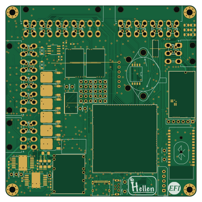
About the Uaefi PCB
Uaefi is an open source PCB design by rusefi, published on GitHub. It is a 4-layer board measuring 100 × 100 mm, with 164 components from 47 distinct parts.
Other key parts include the TLE9201SG, MPX4/MPXH6400_MAP, MAX31855KASA, JDY-33 and VNLD5160TR-E. By type, the board carries 51 resistors, 35 connectors, 33 capacitors, 11 ICs, 10 fuses and 7 modules.
From the project
🔴Community support ONLY 🔴 https://www.facebook.com/groups/rusEfi 🔴 Discord🔴 Commercial Support 🔴
🔴Community support ONLY 🔴 https://www.facebook.com/groups/rusEfi 🔴 Discord🔴 Commercial Support 🔴
Open Source KiCAD hardware powered by Hellen-One
One day we shall try https://jlcpcb.com/partdetail/Stmicroelectronics-STM32F427VIT6%2FC57097#EC or https://jlcpcb.com/partdetail/Stmicroelectronics-STM32F437VIT7%2FC1338578#EC
You would need three files from boards/uaefi-a/board folder to place your JLCPB Assembly order: gerber.zip BOM-JLC.csv and CPL.csv
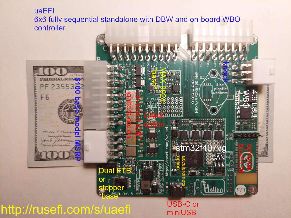
Main components on the Uaefi
Uaefi bill of materials (BOM)
164 components, 47 distinct parts — part numbers from the project's BOM.
| Qty | Part | Footprint | Refs |
|---|---|---|---|
| 2 | TLE9201SG | Infineon_PG-DSO-12-11 | U1, U2 |
| 1 | MPX4/MPXH6400_MAP | MPX-4_MAP | U3 |
| 1 | MAX31855KASA | SOIC-8_3.9x4.9mm_P1.27mm | U4 |
| 1 | JDY-33 | JDY-33 | U5 |
| 6 | VNLD5160TR-E | SOIC-8_3.9x4.9mm_P1.27mm | U6, U7, U8, U9, U10, U11 |
| 1 | Module-power_12and5V-0.3 | power_12and5V | M1 |
| 1 | Module-knock-0.2 | knock | M2 |
| 1 | Module-vr-discrete-0.5 | vr-discrete | M3 |
| 1 | Module-vr-max9924-0.1 | vr-max9924 | M4 |
| 1 | Module-wbo-0.6 | wbo | M5 |
| 1 | Module:mega-mcu100/0.3 | mega-mcu100 | M6 |
| 1 | Module-can-0.1 | can | M7 |
| 6 | ISL9V3040D3ST | TO-252-2 | Q7, Q8, Q9, Q10, Q11, Q12 |
| 14 | CONN_02X02_ODD_EVEN Conn_02x02_Odd_Even | PinSocket_2x02_P2.54mm_Vertical | J1, J11, J12, J13, J14, J15, J16, J17 +6 |
| 1 | 5569-20A2 | Molex_Mini-Fit_Jr_5569-20A2_2x10_P4.20mm_Horizontal | J2 |
| 1 | 5569-06A2 | Molex_Mini-Fit_Jr_5569-06A2_2x03_P4.20mm_Horizontal | J3 |
| 1 | 5569-08A2 | Molex_Mini-Fit_Jr_5569-08A2_2x04_P4.20mm_Horizontal | J4 |
| 1 | 5569-18A2 | Molex_Mini-Fit_Jr_5569-18A2_2x09_P4.20mm_Horizontal | J5 |
| 1 | CONN_01X06 Conn_01x06 | PinHeader_1x06_P2.54mm_Vertical | J6 |
| 1 | CONN_01X05_MALE Conn_01x05_Male | Molex_SPOX_5267-05A_1x05_P2.50mm_Vertical | J7 |
Show 27 more
| Qty | Part | Footprint | Refs |
|---|---|---|---|
| 1 | USB_B_Mini | USB-MINI-B-VERTICAL | J8 |
| 1 | C2927038 USB_C | USB_C | J9 |
| 1 | 39301160 5569-16A2 | Molex_Mini-Fit_Jr_5569-16A2_2x08_P4.20mm_Horizontal | J10 |
| 12 | Pad | PAD-TH | P1, P2, P3, P4, P5, P6, P7, P8 +4 |
| 1 | CR1220 | CR1220-2 | BT1 |
| 4 | 12H1500D Fuse | Fuse_1206_3216Metric_Pad1.42x1.75mm_HandSolder | F1, F2, F3, F4 |
| 6 | 50MA 50mA | Fuse_0603_1608Metric | F5, F6, F7, F8, F9, F10 |
| 2 | PROTO_AREA | PROTO_AREA | G3, G4 |
| 1 | 1N4148WS | SOD-323 | D1 |
| 4 | B5819W | SOD-123 | D2, D3, D4, D5 |
| 1 | NUP2105L | SOT-23 | D8 |
| 2 | 470R@100MHz | L_0603_1608Metric | L1, L2 |
| 20 | 10U 10u | C0805 | C1, C2, C3, C4, C5, C6, C7, C8 +12 |
| 6 | 100N 100n | C0603 | C11, C24, C27, C29, C31, C33 |
| 6 | 10N 10n | C0603 | C12, C13, C25, C26, C28, C30 |
| 1 | 1u | C0603 | C32 |
| 15 | 4.7K 4.7k | R0603 | R1, R9, R10, R11, R12, R13, R14, R15 +7 |
| 1 | 33K 33k | R0603 | R2 |
| 1 | 6.8K 6.8k | R0603 | R3 |
| 1 | C17477 4.7k | R0603 | R4 |
| 2 | 0 | R0603 | R5, R6 |
| 2 | 5.6K 5.6k | R0603 | R7, R8 |
| 6 | 22 | R0603 | R17, R18, R19, R23, R24, R25 |
| 6 | 0 | R_2512_6332Metric | R20, R21, R22, R26, R27, R28 |
| 3 | 10K 10k | R0805 | R35, R36, R37 |
| 3 | DNP | R0805 | R38, R39, R40 |
| 11 | 4.7k | R0603 | R41, R42, R43, R44, R45, R46, R47, R48 +3 |
Uaefi design files
The KiCad project lives in the rusefi/uaefi repository on GitHub; these links point at the commit this page was built from.
- Layoutuaefi.kicad_pcb
- Schematicuaefi.kicad_sch
- BOMboards/uaefi-b/board/misc/uaefi-b-BOM.csv
Uaefi: common questions
How big is the Uaefi PCB?
The Uaefi measures 100 × 100 mm, has 4 copper layers and is 1.6 mm thick.
How many components are on the Uaefi?
164 components, from 47 distinct parts, with part numbers taken from the project's own BOM. The full bill of materials is listed on this page.
Where can I download the Uaefi design files?
From the rusefi/uaefi repository on GitHub, which has the KiCad layout, the schematic and the BOM; the links under Design files point to each one.
Can I use the Uaefi design in my own project?
The repository has no license, so all rights stay with rusefi. Use it as a reference, and ask the author before reusing the design.