
Pico-Breadboard-Kit

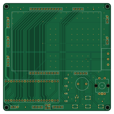
About the Pico-Breadboard-Kit PCB
Pico-Breadboard-Kit is an open source RP2040/RP2350 PCB design by rustemsevik, published on GitHub under the MIT license. It is a 2-layer board measuring 100 × 100 mm, with 32 components from 21 distinct parts.
Its main chip is the Pico, from the RP2040/RP2350 family. Other key parts include the BREADBOARD. By type, the board carries 13 connectors, 5 switches, 5 resistors, 4 LEDs, 2 ICs and 1 transistor.
It belongs with the dev boards & breakouts, robotics & motion and sensors designs in this gallery.
From the project
This is a Raspberry Pi Pico breadboard kit designed for students to learn and experiment with basic electronics and microcontroller programming.
This is a Raspberry Pi Pico breadboard kit designed for students to learn and experiment with basic electronics and microcontroller programming.
- Raspberry Pi Pico with full GPIO breakout - Four tactile buttons connected to GPIOs - Four LEDs with current-limiting resistors - Buzzer controlled via transistor switch - Rotary encoder with push switch for interactive input - Potentiometer connected to ADC input - Headers for external 3.3V and 5V power - Dedicated I2C connector for screen (SCL/SDA) - Connector for MPU6050 (I2C accelerometer/gyroscope) - Servo motor headers (2x) with GPIO control…
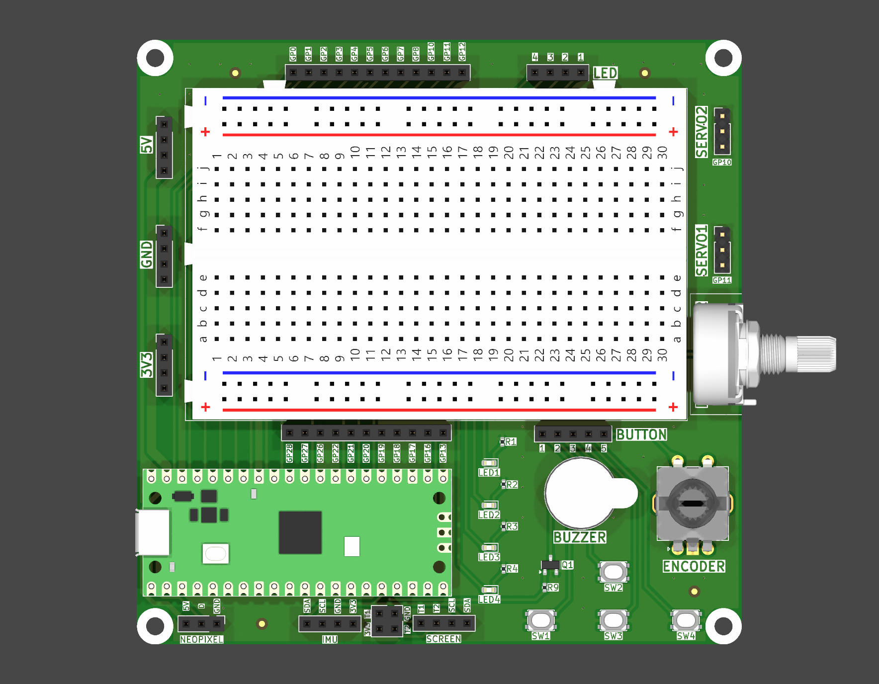
Main components on the Pico-Breadboard-Kit
Pico-Breadboard-Kit bill of materials (BOM)
32 components, 21 distinct parts — part numbers from the project's BOM.
| Qty | Part | Footprint | Refs |
|---|---|---|---|
| 1 | Pico | RPi_Pico_SMD_TH | U1 |
| 1 | BREADBOARD | Breadboard_Half | U2 |
| 1 | BC817 | SOT-23 | Q1 |
| 1 | CONN_01X05 Conn_01x05 | PinSocket_1x05_P2.54mm_Vertical | J1 |
| 1 | LED | PinSocket_1x04_P2.54mm_Vertical_NoPin1Mark | J2 |
| 1 | 5V CONNECTOR | PinSocket_1x04_P2.54mm_Vertical | J3 |
| 1 | GND CONNECTOR | PinSocket_1x04_P2.54mm_Vertical | J4 |
| 1 | 3.3V CONNECTOR | PinSocket_1x04_P2.54mm_Vertical | J5 |
| 1 | CONN_01X12 Conn_01x12 | PinSocket_1x12_P2.54mm_Vertical | J6 |
| 1 | CONN_01X11 Conn_01x11 | PinSocket_1x11_P2.54mm_Vertical | J7 |
| 1 | SCREEN CONNECTOR | PinSocket_1x04_P2.54mm_Vertical_NoPin1Mark | J8 |
| 2 | CONN_01X03 Conn_01x03 | PinHeader_1x03_P2.54mm_Vertical | J9, J11 |
| 1 | MPU6050 CONNECTOR | PinSocket_1x04_P2.54mm_Vertical_NoPin1Mark | J10 |
| 1 | CONN_01X03 Conn_01x03 | PinSocket_1x03_P2.54mm_Vertical | J12 |
| 1 | Polarity Select | PinSocket_2x02_P2.54mm_Vertical | J13 |
| 1 | Buzzer | Buzzer_D12.0mm_P7.60mm | BZ1 |
| 1 | R_Potentiometer | Potentiometer_Omeg_PC16BU_Horizontal | RV1 |
| 4 | SW_SPST | SW_SPST_PTS810 | SW1, SW2, SW3, SW4 |
| 1 | RotaryEncoder_Switch_MP | RotaryEncoder_Alps_EC11E-Switch_Vertical_H20mm | SW5 |
| 4 | LED | LED_0603_1608Metric | LED1, LED2, LED3, LED4 |
Show 1 more
| Qty | Part | Footprint | Refs |
|---|---|---|---|
| 5 | 1k | R_0402_1005Metric | R1, R2, R3, R4, R9 |
Pico-Breadboard-Kit design files
The KiCad project lives in the rustemsevik/pico-Breadboard-Kit repository on GitHub; these links point at the commit this page was built from.
Pico-Breadboard-Kit: common questions
What microcontroller does the Pico-Breadboard-Kit use?
The Pico-Breadboard-Kit is built around the Pico, from the RP2040/RP2350 family.
How big is the Pico-Breadboard-Kit PCB?
The Pico-Breadboard-Kit measures 100 × 100 mm, has 2 copper layers and is 1.6 mm thick.
How many components are on the Pico-Breadboard-Kit?
32 components, from 21 distinct parts, with part numbers taken from the project's own BOM. The full bill of materials is listed on this page.
Where can I download the Pico-Breadboard-Kit design files?
From the rustemsevik/pico-Breadboard-Kit repository on GitHub, which has the KiCad layout, the schematic and the BOM; the links under Design files point to each one.
Can I use the Pico-Breadboard-Kit design in my own project?
Yes, under the terms of its MIT license, which rustemsevik chose for the repository.
Can I test firmware for the Pico-Breadboard-Kit without the hardware?
Yes. HardLabs builds a simulation of the board from its netlist and BOM, so you can run and debug RP2040/RP2350 firmware against it before you order a PCB.
Similar boards
 RP2040/RP2350
OSO-BOOK-C1
joeycastillo
85 × 115 mm29 parts2LCC-BY-SA-4.08.1k RP2040/RP2350
Corne cherry
foostan
277.2 × 107.5 mm164 parts2LCC-BY-4.07.7k RP2040/RP2350
Corne chocolate
277.2 × 107.5 mm164 parts2LCC-BY-4.07.7k RP2040/RP2350
Jitx design
gusmanb
55.5 × 65 mm26 parts4LGPL-3.05.0k RP2040/RP2350
LogicAnalyzer
57 × 55.2 mm6 parts2LGPL-3.05.0k RP2040/RP2350
Main
google
98 × 71 mm102 parts2LApache-2.02.9k