
Battery monitor

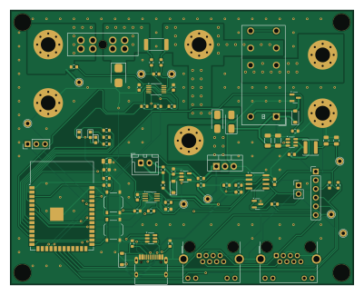
About the Battery monitor PCB
Battery monitor is an open source ESP32 PCB design by ryanabraham1, published on GitHub. It is a 2-layer board measuring 100 × 80 mm, with 72 components from 48 distinct parts.
Its main chip is the Espressif ESP32-S3-WROOM-1-N4, from the ESP32 family. Other key parts include the TI INA226AIDGSR, TI SN65HVD230DR, Diodes AP63203WU-7, TI SN74LVC1G123DCTR and TI UCC27517DBVR. By type, the board carries 24 resistors, 16 capacitors, 10 diodes, 7 ICs, 6 connectors and 2 transistors.
It belongs with the power & battery and iot & wireless designs in this gallery.
From the project
An inline node that sits between a charger and a 12 V FRC battery (charger → node → battery). It measures internal resistance with a 12 A / 100 ms pulse load, and reports to a pit hub over wired CAN. No Wi-Fi or Bluetooth is used.
An inline node that sits between a charger and a 12 V FRC battery (charger → node → battery). It measures internal resistance with a 12 A / 100 ms pulse load, and reports to a pit hub over wired CAN. No Wi-Fi or Bluetooth is used.
Status: schematic and layout are complete (ERC and DRC clean) and ready to order. Node firmware, the Raspberry Pi hub software and printable cases are included. Nothing has been built or tested on real hardware yet: the firmware compiles and the hub passes a simulated-node test.
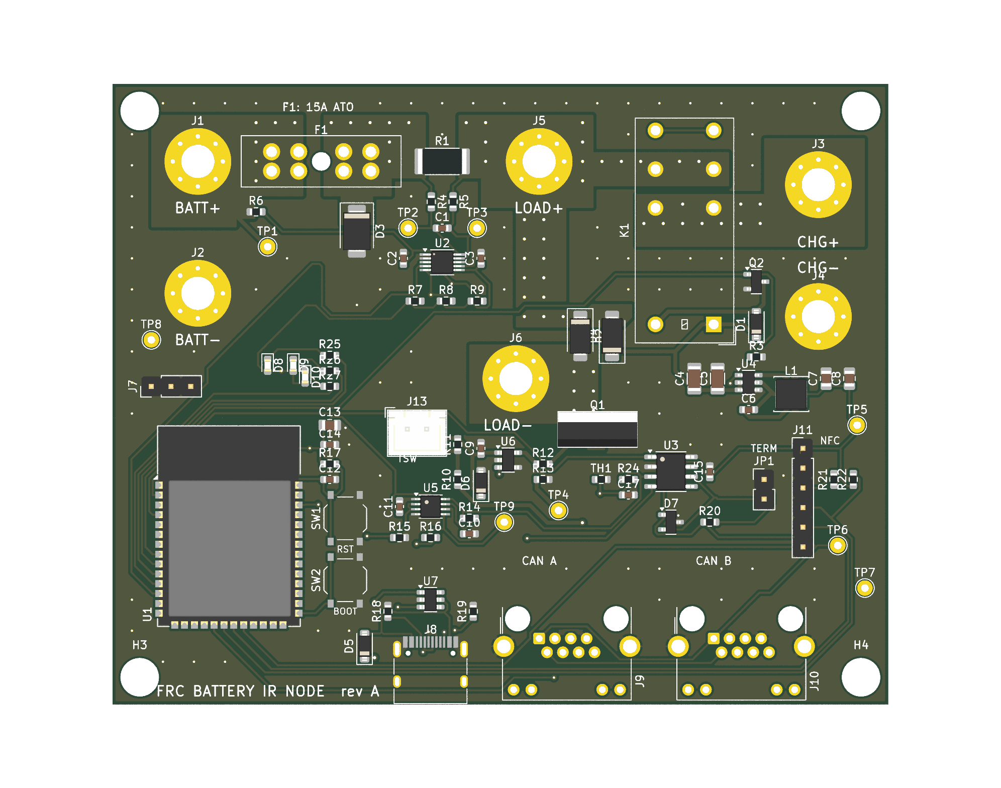
Main components on the Battery monitor
Battery monitor bill of materials (BOM)
72 components, 48 distinct parts — part numbers from the project's BOM.
| Qty | Part | Footprint | Refs |
|---|---|---|---|
| 1 | Espressif ESP32-S3-WROOM-1-N4 ESP32-S3-WROOM-1-N4 | ESP32-S3-WROOM-1 | U1 |
| 1 | TI INA226AIDGSR INA226AIDGSR (INA228 drop-in) | VSSOP-10_3x3mm_P0.5mm | U2 |
| 1 | TI SN65HVD230DR SN65HVD230DR | SOIC-8_3.9x4.9mm_P1.27mm | U3 |
| 1 | Diodes AP63203WU-7 AP63203WU-7 | TSOT-23-6 | U4 |
| 1 | TI SN74LVC1G123DCTR SN74LVC1G123DCTR | SSOP-8_2.95x2.8mm_P0.65mm | U5 |
| 1 | TI UCC27517DBVR UCC27517DBVR | SOT-23-5 | U6 |
| 1 | ST USBLC6-2SC6 USBLC6-2SC6 | SOT-23-6 | U7 |
| 1 | Infineon IRLB3034PBF IRLB3034PBF | TO-220-3_Vertical | Q1 |
| 1 | AOS AO3400A AO3400A | SOT-23 | Q2 |
| 1 | 2.54mm header 1x3 UART0 debug | PinHeader_1x03_P2.54mm_Vertical | J7 |
| 1 | HRO TYPE-C-31-M-12 USB-C | USB_C_Receptacle_HRO_TYPE-C-31-M-12 | J8 |
| 1 | Connfly DS1128-09-S8B8X CAN A | RJ45_Connfly_DS1128-09-S8xx-S_Horizontal | J9 |
| 1 | Connfly DS1128-09-S8B8X CAN B | RJ45_Connfly_DS1128-09-S8xx-S_Horizontal | J10 |
| 1 | 2.54mm header 1x6 (optional) optional: PN532 NFC reader (I2C) | PinHeader_1x06_P2.54mm_Vertical | J11 |
| 1 | XH-2A TSW: NC thermostat on the load resistor (required) | JST_XH_B2B-XH-A_1x02_P2.50mm_Vertical | J13 |
| 1 | Littelfuse 178.6165.0002 ATO 15A in FLR holder | FuseHolder_Blade_ATO_Littelfuse_FLR_178.6165 | F1 |
| 1 | 2.54mm header 1x2 + jumper cap TERM jumper | PinHeader_1x02_P2.54mm_Vertical | JP1 |
| 1 | Omron G2RL-1-E-DC12 G2RL-1-E-DC12 | Relay_SPDT_Omron_G2RL-1-E | K1 |
| 1 | XKB TS-1187A-B-A-B RESET | SW_Push_1P1T_XKB_TS-1187A | SW1 |
| 1 | XKB TS-1187A-B-A-B BOOT | SW_Push_1P1T_XKB_TS-1187A | SW2 |
Show 28 more
| Qty | Part | Footprint | Refs |
|---|---|---|---|
| 1 | KUU KNTC0603/10KF3950 10k B3950 1% | R_0603_1608Metric | TH1 |
| 1 | 1N4148W | D_SOD-123 | D1 |
| 1 | MDD SS54 SS54 | D_SMA | D2 |
| 1 | BORN SMBJ20A SMBJ20A | D_SMB | D3 |
| 1 | MDD SS34 SS34 | D_SMA | D4 |
| 1 | B5819W | D_SOD-123 | D5 |
| 1 | BZT52C12 | D_SOD-123 | D6 |
| 1 | UMW PESD2CAN PESD2CAN | SOT-23 | D7 |
| 1 | KENTO KT-0603R RED | LED_0603_1608Metric | D8 |
| 1 | KENTO KT-0603G GREEN | LED_0603_1608Metric | D9 |
| 1 | KENTO KT-0603B BLUE | LED_0603_1608Metric | D10 |
| 1 | Sunlord SWPA4030S4R7MT 4.7uH 2A | L_Sunlord_SWPA4030S | L1 |
| 8 | 100N 100n | C_0603_1608Metric | C1, C2, C3, C6, C11, C14, C15, C17 |
| 2 | C13585 10u 50V | C_1206_3216Metric | C4, C5 |
| 3 | C45783 22u 25V | C_0805_2012Metric | C7, C8, C13 |
| 2 | C15849 1u 50V | C_0603_1608Metric | C9, C12 |
| 1 | C23630 2u2 16V | C_0603_1608Metric | C10 |
| 1 | RALEC LR2512-22R001F4 1mR 1% 2W 75ppm | R_2512_6332Metric | R1 |
| 6 | 10K 10k | R_0603_1608Metric | R3, R9, R13, R15, R17, R24 |
| 2 | 4R7 | R_0603_1608Metric | R4, R5 |
| 2 | 10R | R_0603_1608Metric | R6, R12 |
| 4 | 4K7 4k7 | R_0603_1608Metric | R7, R8, R21, R22 |
| 2 | 470R | R_0603_1608Metric | R10, R25 |
| 1 | 100K 100k | R_0603_1608Metric | R14 |
| 1 | 1k | R_0603_1608Metric | R16 |
| 2 | 5K1 5k1 | R_0603_1608Metric | R18, R19 |
| 1 | 120R | R_0603_1608Metric | R20 |
| 2 | 100R | R_0603_1608Metric | R26, R27 |
Battery monitor design files
The KiCad project lives in the ryanabraham1/battery-monitor repository on GitHub; these links point at the commit this page was built from.
- Layouthw/ir_node.kicad_pcb
- Schematichw/ir_node.kicad_sch
- BOMfab/ir_node_BOM_full.csv
Battery monitor: common questions
What microcontroller does the Battery monitor use?
The Battery monitor is built around the Espressif ESP32-S3-WROOM-1-N4, from the ESP32 family.
How big is the Battery monitor PCB?
The Battery monitor measures 100 × 80 mm, has 2 copper layers and is 1.6 mm thick.
How many components are on the Battery monitor?
72 components, from 48 distinct parts, with part numbers taken from the project's own BOM. The full bill of materials is listed on this page.
Where can I download the Battery monitor design files?
From the ryanabraham1/battery-monitor repository on GitHub, which has the KiCad layout, the schematic and the BOM; the links under Design files point to each one.
Can I use the Battery monitor design in my own project?
The repository has no license, so all rights stay with ryanabraham1. Use it as a reference, and ask the author before reusing the design.
Can I test firmware for the Battery monitor without the hardware?
Yes. HardLabs builds a simulation of the board from its netlist and BOM, so you can run and debug ESP32 firmware against it before you order a PCB.
Similar boards
 ESP32
OSO-BOOK-B1
joeycastillo
85 × 115 mm65 parts2LCC-BY-SA-4.08.1k ESP32
Powertrain
byrantech
64 × 45.4 mm171 parts4LMIT4.3k ESP32
Badge
atopile
56.3 × 39 mm239 parts4LMIT4.0k ESP32
Esp32 minimal
36.2 × 26.8 mm20 parts2LMIT4.0k ESP32
Controller
StuckAtPrototype
29 × 74 mm58 parts4LApache-2.03.8k ESP32
Racer
36 × 50.2 mm70 parts4LApache-2.03.8k