
Autonomous Ackermann

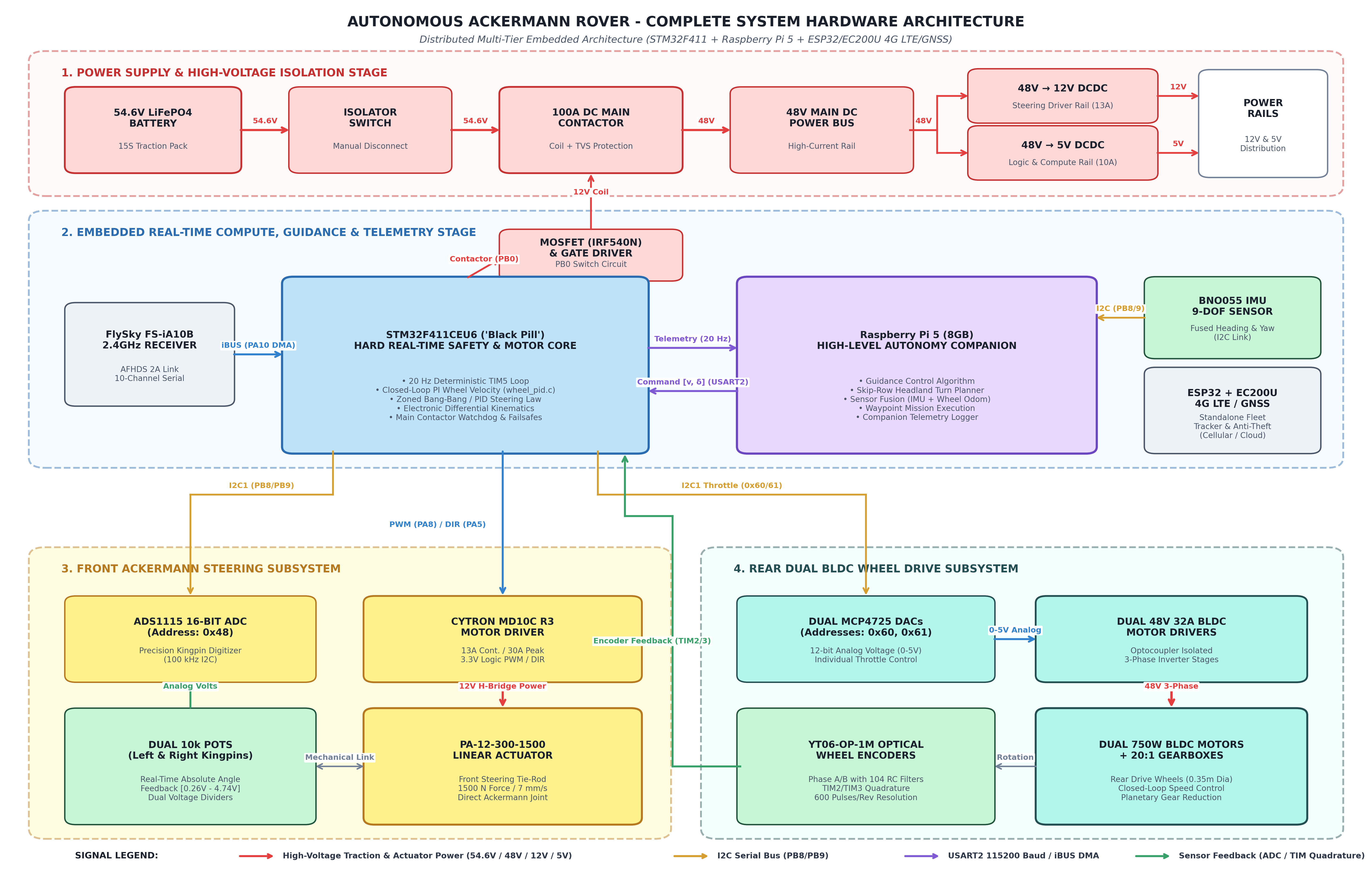
About the Autonomous Ackermann PCB
Autonomous Ackermann is an open source STM32 PCB design by sachu018, published on GitHub. It is a board, with 97 components from 36 distinct parts.
Its main chip is the STM32F411CEUx, from the STM32 family. Other key parts include the PC817, CY_Controller_48V, MCP4725, HiLink_48V_5V and TLP250. By type, the board carries 47 resistors, 26 ICs, 4 modules, 2 transistors, 2 connectors and 2 switches.
It belongs with the robotics & motion designs in this gallery.
From the project
Agricultural rover: STM32 closed-loop Ackermann steering + Raspberry Pi 5 autonomous companion computer
Modern precision agriculture relies on autonomous unmanned ground vehicles (UGVs) to execute labour-intensive field tasks such as row monitoring, precision spraying, and selective weeding.
This repository houses the complete electrical architecture, bare-metal C firmware, PCB design files, and Python autonomy stack developed to transform a legacy, open-loop BeagleBone Black differential-drive rover into a distributed, closed-loop STM32F411 + Raspberry Pi 5 Ackermann-steering autonomous agricultural rover.
Main components on the Autonomous Ackermann
Autonomous Ackermann bill of materials (BOM)
97 components, 36 distinct parts.
| Qty | Part | Footprint | Refs |
|---|---|---|---|
| 8 | PC817 | DIP-4_W7.62mm | U1, U2, U7, U9, U16, U17, U18, U19 |
| 2 | CY_Controller_48V | U3, U8 | |
| 4 | MCP4725 | SOT-23-6 | U4, U5, U14, U36 |
| 1 | HiLink_48V_5V | U6 | |
| 2 | TLP250 | DIP-8_W7.62mm | U10, U13 |
| 1 | HiLink_48V_5V | URA&slash_URB_LD-30WR3_MNS | U11 |
| 1 | HiLink_48V_12V | U12 | |
| 4 | Level Shifter | SOT-23-6 | U15, U20, U22, U23 |
| 1 | FS_IA10B | Samtec_HPM-03-01-x-S_Straight_1x03_Pitch5.08mm | U21 |
| 1 | ADS1115IDGS | TSSOP-10_3x3mm_P0.5mm | U24 |
| 1 | STM32F411CEUx | QFN-48-1EP_7x7mm_P0.5mm_EP5.6x5.6mm | U25 |
| 2 | BLDC_3PH_HALL | M2, M3 | |
| 1 | BEAGLEBONEBLACK | MODULE_BEAGLEBONEBLACK | M4 |
| 1 | DC Contactor | M5 | |
| 2 | IRF540N | TO-220-3_Vertical | Q1, Q2 |
| 1 | 48V to 5V Non_isolated supply | SOIC-8_3.9x4.9mm_P1.27mm | J1 |
| 1 | Raspberry_Pi_5(External) | RaspberryPi_Pico_W_SMD | J2 |
| 2 | C | 0.1uf, 0.1uf1 | |
| 2 | C_Polarized | 47uf, 47uf2 | |
| 1 | EV_48V_12V | 48V_to_12V |
Show 16 more
| Qty | Part | Footprint | Refs |
|---|---|---|---|
| 1 | Battery Charger 15s | BC1 | |
| 1 | 48V | BT1 | |
| 1 | H_bridge_driver | J_MD10C | |
| 1 | Left_Feedback | RV1 | |
| 1 | Right_feedback | RV2 | |
| 1 | FS-iA10B | RX1 | |
| 2 | BATTERY ISOLATOR SWITCH | SW1, SW2 | |
| 2 | SR100MDD | D1, D2 | |
| 1 | 100uf | C4 | |
| 10 | 470 | R1, R2, R3, R7, R8, R13, R18, R19 +2 | |
| 2 | 10 | R4, R14 | |
| 20 | 10K | R5, R6, R11, R12, R15, R16, R17, R20 +12 | |
| 10 | 4.7k | R9, R10, R31, R32, R33, R34, R48, R49 +2 | |
| 2 | 1k | R27, R35 | |
| 2 | 2k | R28, R36 | |
| 1 | 10K_Pull_up | R37 |
Autonomous Ackermann design files
The KiCad project lives in the sachu018/Autonomous_Ackermann repository on GitHub; these links point at the commit this page was built from.
- SchematicHardware_KiCad/kicad_setup.kicad_sch
Autonomous Ackermann: common questions
What microcontroller does the Autonomous Ackermann use?
The Autonomous Ackermann is built around the STM32F411CEUx, from the STM32 family.
How many components are on the Autonomous Ackermann?
97 components, from 36 distinct parts. The full bill of materials is listed on this page.
Where can I download the Autonomous Ackermann design files?
From the sachu018/Autonomous_Ackermann repository on GitHub, which has the schematic; the links under Design files point to each one.
Can I use the Autonomous Ackermann design in my own project?
The repository has no license, so all rights stay with sachu018. Use it as a reference, and ask the author before reusing the design.
Can I test firmware for the Autonomous Ackermann without the hardware?
Yes. HardLabs builds a simulation of the board from its netlist and BOM, so you can run and debug STM32 firmware against it before you order a PCB.
Similar boards
 STM32
STM32LumenPnP Motherboard
opulo-inc
149 × 95 mm296 parts4LCC-BY-SA-4.03.7k STM32
STM32Type c
google
188 × 30 mm17 parts2LApache-2.02.9k STM32
STM32Main panel
234 × 84 mm26 parts4LApache-2.02.9k STM32
STM32Base
52.3 × 52.3 mm36 parts2LApache-2.02.9k STM32
STM32Type a
150 × 30 mm14 parts2LApache-2.02.9k STM32
STM32Type e
140.5 × 30 mm13 parts2LApache-2.02.9k