
146 open source boards using the ADS1115IDGS
Real designs built with the ADS1115IDGS, from public GitHub projects: a quick way to see how others power, decouple and connect it. Each board comes with its KiCad files, full parts list and a render — and you can simulate its firmware on HardLabs.
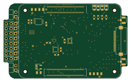 Raspberry Pi
Bcflight
dridri
66.3 × 40.2 mm56 parts4LGPL-3.0169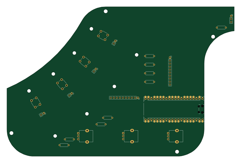 RP2040/RP2350
Stradex1
Bylin-code
192.1 × 126.9 mm24 parts4LNo license101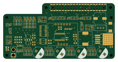 Raspberry Pi
Expansion board
reubenstr
100 × 49.8 mm75 parts4LMIT51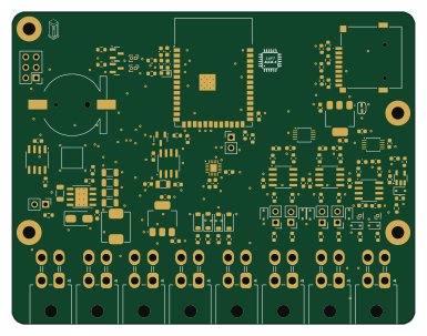 ESP32
Monolith
luftaquila
96 × 74.4 mm112 parts2LCustom license43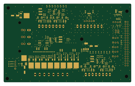
UPD-board
uniclogs
140.7 × 86.5 mm184 parts2LGPL-3.031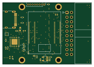
HFLink
LX050724
48.5 × 33.5 mm111 parts4LApache-2.024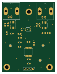
PH Orp Board
Loic74650
47 × 62.1 mm44 parts2LMIT20- schematic only · 25 partsRaspberry Pi
Interfacing-Laptop-Battery-With-RaspberryPi
omarKmekkawy
25 partsNo license18 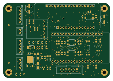 ESP32
IoT12 Control Board
atoomnetmarc
99.1 × 69.9 mm66 parts2LApache-2.014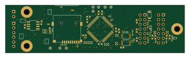 STM32
DiveCAN Head2
QuickRecon
97.1 × 26 mm135 parts4LMIT13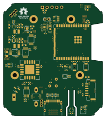 ESP32
ESPHome-Indoor-Multi-Sensor
mikelawrence
52.5 × 59.7 mm97 parts4LCERN-OHL-P-2.012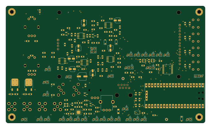 RP2040/RP2350
YamhillFrontPanel
NT7S
170 × 100 mm207 parts4LNo license9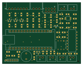 AVR/Arduino
Controller board
andia89
69 × 54 mm73 parts2LNo license6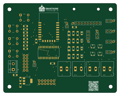 ESP8266
Bewaesserung
SmartHome-yourself
96.5 × 76.2 mm57 parts2LGPL-2.06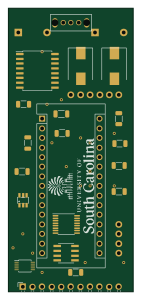 AVR/Arduino
Smart penetrometer v0.4.0
ARTS-Laboratory
33 × 74.9 mm44 parts2LCC-BY-SA-4.06- schematic only · 24 parts
Opentdcs
nathanfu88
24 partsCustom license5 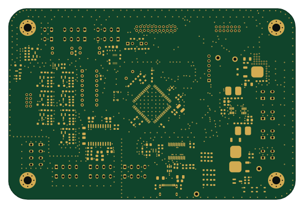 AVR/Arduino
SatelliteController2.0
tokai-student-rocket-project
150 × 100 mm221 parts2LMIT2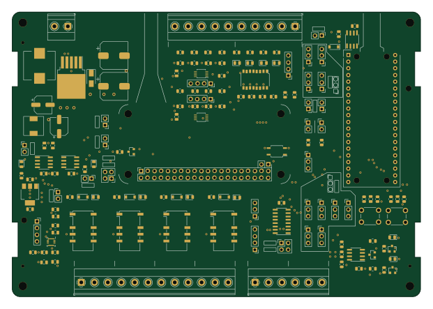 RP2040/RP2350
Nyu openplc te
kiwih
155 × 108 mm153 parts2LGPL-3.02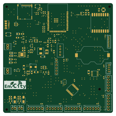 ESP32
Aqm envcity hw
MateusMaruzka
100 × 100 mm132 parts2LNo license2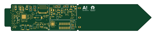 ESP32
Plant-Health-Meter
MarkusVLA
136.2 × 25 mm94 parts4LMIT2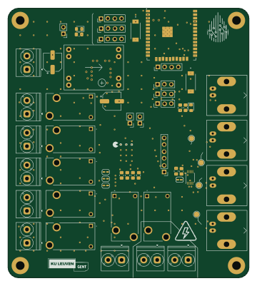 ESP32
PCB Watersysteem
Vertical-Farming-IB3
89.3 × 100 mm88 parts2LNo license2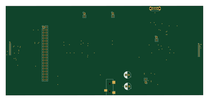
Handheld Gaming device
DhairyaAPImaster
180.5 × 81.8 mm60 parts2LNo license2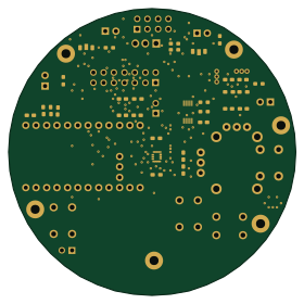
Deltavr controller
oxy-2
70 × 70 mm46 parts2LMIT2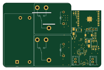 ESP32
30a water heater controller
flaviut
85 × 56 mm42 parts2LCERN-OHL-S-2.02
Sun sensor
vatsalbansal123
26 × 19 mm25 parts2LNo license2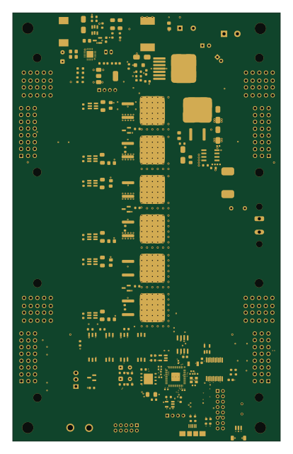 RP2040/RP2350
Solarpump
rivimey
100 × 160 mm424 parts4LNo license1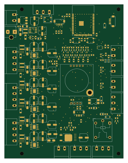 ESP32
HabitatControl hardware
machadoleonardo94
100.6 × 131 mm155 parts2LNo license1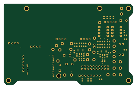
FD PCB
CaptainOrangeSparrow
113.7 × 71.6 mm146 parts2LNo license1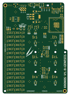 ESP32
Kronos-Hardware
AddeyX
65.6 × 91.8 mm144 parts4LNo license1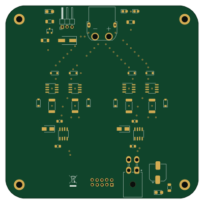 AVR/Arduino
TEC2
Oerdna
100 × 100 mm108 parts4LAGPL-3.01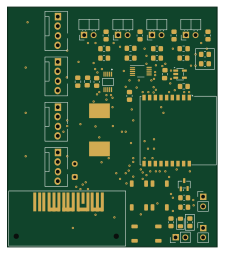 ESP32
Water cooling controller
diablo4338
55.6 × 63.5 mm84 parts2LMIT1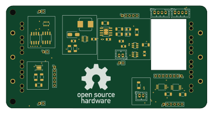
Whole
Benedikt3141
109 × 55.5 mm83 parts2LMIT1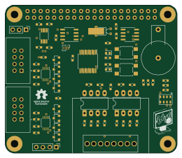
PiADC2
capconix
65 × 56 mm70 parts2LNo license1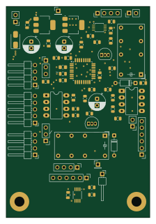 STM32
Electronicload
GM4AJK
54.5 × 80 mm62 parts4LNo license1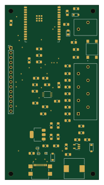 ESP32
ZTank
akira215
49 × 91 mm60 parts2LGPL-3.01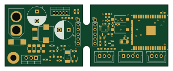 ESP32
Batmon
pjaos
87 × 33 mm57 parts2LMIT1
How designs wire the ADS1115IDGS
Read from the KiCad layouts of 92 open source designs, one per repository: what each pin of the ADS1115IDGS connects to, and the resistors, capacitors and other passives placed on it.
- The VDD pin has a decoupling capacitor on 59 of 90 designs, most often 100 nF (then 1 µF).
- The SDA pin has a pull-up to 3.3V on 59 of 90 designs, most often 4.7 kΩ (then 10 kΩ).
- The SCL pin has a pull-up to 3.3V on 59 of 90 designs, most often 4.7 kΩ (then 10 kΩ).
- The AIN0 pin has a series resistor on 43 of 91 designs, most often 10 kΩ (then 1 kΩ).
| Pin | Connected to | Parts on the pin |
|---|---|---|
| ALERT/RDYpin 2 | Connected to: Signal 54% · not connected 43% |
|
| GNDpin 3 | Connected to: GND 87% | — |
| AIN0pin 4 | Connected to: A connector 26% |
|
| AIN1pin 5 | Connected to: A connector 24% |
|
| AIN2pin 6 | Connected to: A connector 24% · not connected 21% |
|
| AIN3pin 7 | Connected to: A connector 23% · not connected 22% |
|
| VDDpin 8 | Connected to: 3.3V 77% · a signal 23% |
|
| SDApin 9 | Connected to: The microcontroller 51%, a connector 40% |
|
| SCLpin 10 | Connected to: The microcontroller 51%, a connector 40% |
|
1 more pin varies from design to design. Connections count pins, parts count designs; values in brackets are how many parts had that value. Designs read include Bcflight by dridri, Stradex1 by Bylin-code, Day 03 ECG SPO2 by i2cjak and Expansion board by reubenstr.
The ADS1115IDGS in open source designs
The gallery holds 146 open source boards using the ADS1115IDGS from 106 GitHub repositories; a typical one measures about 80.8 × 73.8 mm and carries around 70 components.
59% are two-layer designs, the rest use four layers or more, and 43% carry an open source license.
The most starred is Bcflight by dridri.
Parts used alongside the ADS1115IDGS
Microcontrollers on boards using the ADS1115IDGS
What boards using the ADS1115IDGS are built for
ADS1115IDGS: common questions
Where can I find a ADS1115IDGS reference design?
Each of the 146 boards on this page is a real design using the ADS1115IDGS. Open one to see how it is wired up, with the full BOM, a render of the layout and links to its KiCad files.
What decoupling capacitors do designs use on the ADS1115IDGS VDD pin?
The VDD pin has a decoupling capacitor on 59 of 90 designs, most often 100 nF (then 1 µF). Counted from the KiCad layouts of 92 open source designs using the ADS1115IDGS.
What pull-up resistor is used on the ADS1115IDGS SDA pin?
The SDA pin has a pull-up to 3.3V on 59 of 90 designs, most often 4.7 kΩ (then 10 kΩ). Counted from the KiCad layouts of 92 open source designs using the ADS1115IDGS.
What pull-up resistor is used on the ADS1115IDGS SCL pin?
The SCL pin has a pull-up to 3.3V on 59 of 90 designs, most often 4.7 kΩ (then 10 kΩ). Counted from the KiCad layouts of 92 open source designs using the ADS1115IDGS.
What parts are used alongside the ADS1115IDGS?
The AMS1117-3.3, ESP32-S3-WROOM-1, AP2112K-3.3, CH340C and PC817 appear in the most repositories here.
Which microcontrollers do boards using the ADS1115IDGS use?
Most are built on ESP32 (59), AVR/Arduino (17), STM32 (9) and RP2040/RP2350 (8).
How big is a typical board using the ADS1115IDGS?
The median is 80.8 × 73.8 mm, and 59% are two-layer designs.
What is the most popular open source board using the ADS1115IDGS?
By GitHub stars, Bcflight by dridri, with 169 stars.
Can I simulate one of these boards using the ADS1115IDGS before building it?
Yes. HardLabs turns a board's netlist and BOM into a working simulation, so you can boot and test firmware against it with no hardware on your desk.