
Nerf timer

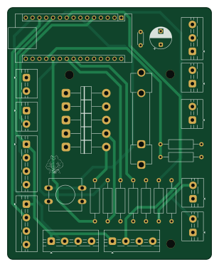
About the Nerf timer PCB
Nerf timer is an open source AVR/Arduino PCB design by Salted-Peanuts, published on GitHub under the MIT license. It is a 4-layer board measuring 75.9 × 93.5 mm, with 30 components from 19 distinct parts.
Its main chip is the ARDUINO_NANO_ESP32, from the AVR/Arduino family. Other key parts include the 5V_STEP_UP. By type, the board carries 9 resistors, 7 diodes, 4 switches, 2 capacitors, 1 IC and 1 module.
It belongs with the iot & wireless and displays & leds designs in this gallery.
From the project
DIY Arduino Nano ESP32 King of the Hill timer for Nerf, foam flinging, skirmish games, and objective-based events. Includes build guide, firmware, BOM, schematic, and phone referee UI.
This folder contains the first manufactured PCB design for the KOTH Timer.
Manufactured and partially working, but not recommended for new builds.
PCB v0.1 has been manufactured and the timer is functional through the web UI, but this revision has known display reliability issues.
Interference Flickering Incorrect segments Unstable or inconsistent output
The main timer logic and web interface can still function, but the display behaviour is not reliable enough for this revision to be recommended as the main PCB build.
Main components on the Nerf timer
Nerf timer bill of materials (BOM)
30 components, 19 distinct parts — part numbers from the project's BOM.
| Qty | Part | Footprint | Refs |
|---|---|---|---|
| 1 | 5V_STEP_UP 5v_Step_Up | TerminalBlock_MaiXu_MX126-5.0-03P_1x03_P5.00mm | U1 |
| 1 | ARDUINO_NANO_ESP32 Arduino_Nano_ESP32 | Arduino_Nano | A1 |
| 1 | 18650_CELL 18650_Cell | TerminalBlock_MaiXu_MX126-5.0-02P_1x02_P5.00mm | BT1 |
| 1 | 2.5-3A_FUSE 2.5-3A_Fuse | Fuseholder_Clip-6.3x32mm_Littelfuse_102_122_Inline_P34.21x7.62mm_D1.98mm_Horizontal | F1 |
| 1 | Rocker_Switch | TerminalBlock_MaiXu_MX126-5.0-02P_1x02_P5.00mm | SW1 |
| 1 | Push_Switch (Team_A) | TerminalBlock_MaiXu_MX126-5.0-02P_1x02_P5.00mm | SW2 |
| 1 | Push_Switch (Team_B) | TerminalBlock_MaiXu_MX126-5.0-02P_1x02_P5.00mm | SW3 |
| 1 | SW_Push | SW_PUSH-12mm | SW4 |
| 2 | 4_Digit_DIsplay (Team_A) | TerminalBlock_MaiXu_MX126-5.0-04P_1x04_P5.00mm | TM1637-A1, TM1637-A2 |
| 2 | 4_Digit_DIsplay (Team_B) | TerminalBlock_MaiXu_MX126-5.0-04P_1x04_P5.00mm | TM1637-B1, TM1637-B2 |
| 1 | LED (Team_A) | TerminalBlock_MaiXu_MX126-5.0-02P_1x02_P5.00mm | D1 |
| 1 | LED (Team_B) | TerminalBlock_MaiXu_MX126-5.0-02P_1x02_P5.00mm | D2 |
| 1 | LED_RED | CUSTLED | D3 |
| 1 | LED_YELLOW | CUSTLED | D4 |
| 3 | LED_GREEN | CUSTLED | D5, D6, D7 |
| 1 | 470UF_E_CAP 470uf_E_Cap | CP_Radial_D8.0mm_P5.00mm | C1 |
| 1 | 0.1UF_C_CAP 0.1uf_C_Cap | C_Disc_D4.3mm_W1.9mm_P5.00mm | C2 |
| 2 | 100K | R_Axial_DIN0309_L9.0mm_D3.2mm_P15.24mm_Horizontal | R1, R2 |
| 7 | 220R | R_Axial_DIN0309_L9.0mm_D3.2mm_P15.24mm_Horizontal | R3, R4, R5, R6, R7, R8, R9 |
Nerf timer design files
The KiCad project lives in the Salted-Peanuts/KOTH-Timer repository on GitHub; these links point at the commit this page was built from.
Nerf timer: common questions
What microcontroller does the Nerf timer use?
The Nerf timer is built around the ARDUINO_NANO_ESP32, from the AVR/Arduino family.
How big is the Nerf timer PCB?
The Nerf timer measures 75.9 × 93.5 mm, has 4 copper layers and is 1.6 mm thick.
How many components are on the Nerf timer?
30 components, from 19 distinct parts, with part numbers taken from the project's own BOM. The full bill of materials is listed on this page.
Where can I download the Nerf timer design files?
From the Salted-Peanuts/KOTH-Timer repository on GitHub, which has the KiCad layout, the schematic and the BOM; the links under Design files point to each one.
Can I use the Nerf timer design in my own project?
Yes, under the terms of its MIT license, which Salted-Peanuts chose for the repository.
Can I test firmware for the Nerf timer without the hardware?
Yes. HardLabs builds a simulation of the board from its netlist and BOM, so you can run and debug AVR/Arduino firmware against it before you order a PCB.
More boards in KOTH-Timer
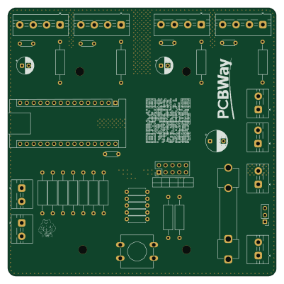
Similar boards
 AVR/Arduino
Magspoof
samyk
35 × 29 mm11 parts2LNo license4.2k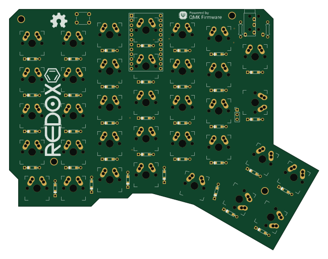 AVR/Arduino
Redox keyboard
mattdibi
162.2 × 126.5 mm77 parts2LMIT2.0k AVR/Arduino
Labrador
espotek-org
36.8 × 34.7 mm75 parts2LNo license1.2k AVR/Arduino
ModuleV450
stuartpittaway
30 × 61.4 mm39 parts2LCC-BY-NC-4.01.1k AVR/Arduino
V4
30 × 50 mm38 parts2LCC-BY-NC-4.01.1k AVR/Arduino
Discipline
coseyfannitutti
304.9 × 122.8 mm170 parts2LCC-BY-NC-4.01.0k