
Vibrator


About the Vibrator PCB
Vibrator is an open source PCB design by SeanCarr1, published on GitHub. It is a 2-layer board measuring 21 × 12.1 mm, with 12 components from 6 distinct parts.
By type, the board carries 4 resistors, 2 transistors and 2 capacitors.
From the project
A compilation of my KiCad projects from school to personal projects
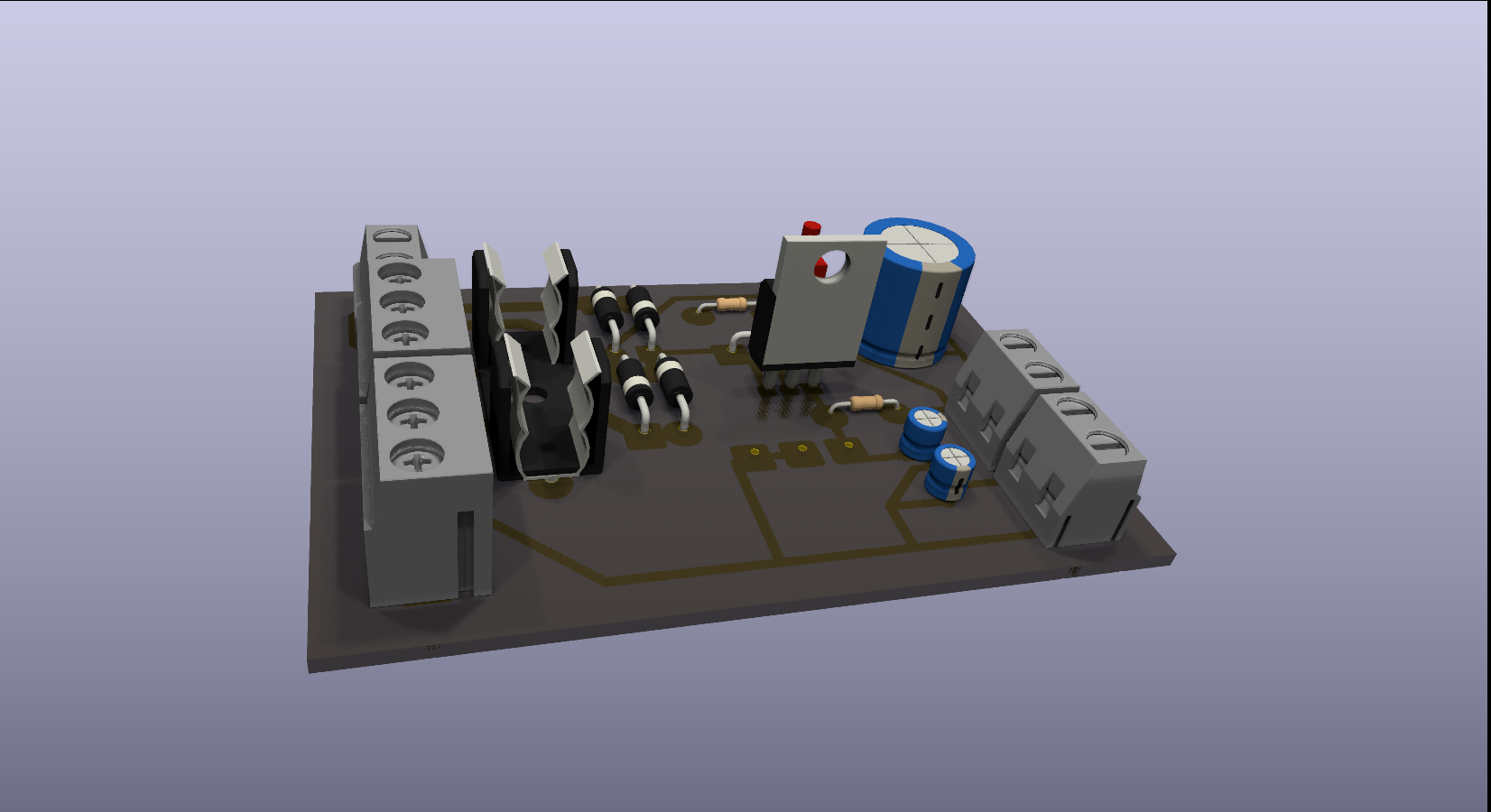
Vibrator bill of materials (BOM)
12 components, 6 distinct parts — part numbers from the project's BOM.
| Qty | Part | Footprint | Refs |
|---|---|---|---|
| 2 | BC547 | TO-92_Wide | Q1, Q2 |
| 4 | Conn_01x01_Pin | PinHeader_1x01_P1.00mm_Vertical | PSU_GND1, PSU_VCC1, Piezo_+1, Piezo_+2 |
| 1 | 300pF | C_Disc_D3.0mm_W1.6mm_P2.50mm | C1 |
| 1 | 82pF | C_Disc_D3.0mm_W1.6mm_P2.50mm | C2 |
| 2 | 10k | R_Axial_DIN0207_L6.3mm_D2.5mm_P7.62mm_Horizontal | R1, R3 |
| 2 | 560k | R_Axial_DIN0207_L6.3mm_D2.5mm_P10.16mm_Horizontal | R2, R4 |
Vibrator design files
The KiCad project lives in the SeanCarr1/KiCad-seancarr1 repository on GitHub; these links point at the commit this page was built from.
Vibrator: common questions
How big is the Vibrator PCB?
The Vibrator measures 21 × 12.1 mm, has 2 copper layers and is 1.6 mm thick.
How many components are on the Vibrator?
12 components, from 6 distinct parts, with part numbers taken from the project's own BOM. The full bill of materials is listed on this page.
Where can I download the Vibrator design files?
From the SeanCarr1/KiCad-seancarr1 repository on GitHub, which has the KiCad layout, the schematic and the BOM; the links under Design files point to each one.
Can I use the Vibrator design in my own project?
The repository has no license, so all rights stay with SeanCarr1. Use it as a reference, and ask the author before reusing the design.
More boards in KiCad-seancarr1
Password
48.3 × 31.6 mm30 parts2LNo license0
Water
20.3 × 12.4 mm21 parts2LNo license0
Dice
72.1 × 26.4 mm21 parts2LNo license0
Asdf
76.2 × 50.8 mm20 parts2LNo license0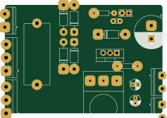
PSU 10-13
59.3 × 40.9 mm20 parts2LNo license0
Act3
23.1 × 24.1 mm17 parts2LNo license0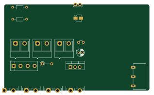
Kicadpartsplacer
79.3 × 46.9 mm17 parts2LNo license0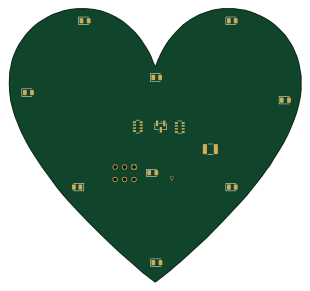
Heart pcb 2
77.3 × 72.3 mm16 parts2LNo license0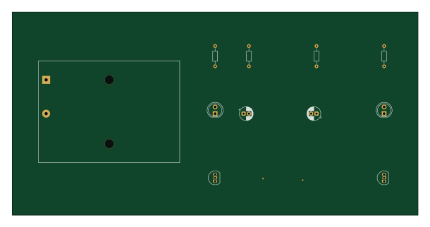
Project1
152.4 × 76.2 mm11 parts2LNo license0
Dark sensor
19.6 × 19.3 mm7 parts2LNo license0
4017
12.5 × 9.3 mm3 parts2LNo license0