
Potentiostat

About the Potentiostat PCB
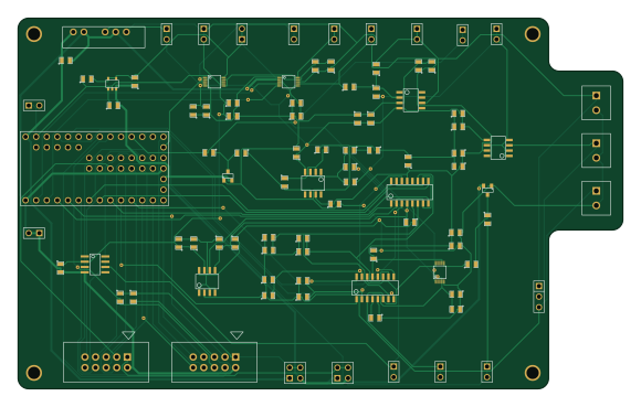
Potentiostat is an open source NXP PCB design by selvanair, published on GitHub under the CC-BY-4.0 license. It is a 2-layer board measuring 144.8 × 88.9 mm, with 99 components from 34 distinct parts.
Its main chip is the WM17453, from the NXP family. Other key parts include the ZXRE060ET5DI, MAX6176AASA+, LT1995, AD8250ARMZ-R7 and 811-2678-5. By type, the board carries 39 capacitors, 21 connectors, 19 resistors, 13 ICs, 2 diodes and 1 relay.
It belongs with the dev boards & breakouts designs in this gallery.
From the project
Hardware design, firmware and software for IO Rodeo's Potentiostat Shield.
Hardware design, firmware and software for IO Rodeo's Potentiostat Shield.
Designed as a shield for teensy 3.2 development board. 12-bit voltage output with four range settings: +/- 1, 2, 5, 10V 16-bit current measurement with four range settings: +/- 1, 10, 100, 1000 uA ranges Can be programmed over USB using the Arduino IDE (teensyduino). Expansion headers with DIO, analog inputs, UART, I2C, and SPI Schematic

Main components on the Potentiostat
Potentiostat bill of materials (BOM)
99 components, 34 distinct parts — part numbers from the project's BOM.
| Qty | Part | Footprint | Refs |
|---|---|---|---|
| 1 | ZXRE060ET5DI ZXRE060 Digikey | SOT23-5 | U1 |
| 1 | WM17453 TEENSY3.1 Digikey | TEENSY3X | U2 |
| 1 | MAX6176AASA+ Digikey | MAXIM-S8 | U3 |
| 2 | LT1995 Digikey | MSOP10-0.5 | U4, U12 |
| 1 | AD8250ARMZ-R7 AD8250 Digikey | MSOP10-0.5 | U5 |
| 1 | 811-2678-5 MEA1D05XXSC Digikey | MEA1 | U6 |
| 2 | OPA129U OPA129 Digikey | 8-SOIC-0154 | U7, U8 |
| 2 | ADG441BRZ-REEL ADG44X Digikey | 16-SOIC-0154 | U9, U13 |
| 1 | 296-26248-1 OPA227 Digikey | 8-SOIC-0154 | U10 |
| 1 | 296-14626-1 OP07 Digikey | 8-SOIC-0154 | U11 |
| 3 | ED2635 CONN_2 Digikey | CONNBLOCK2 | P1, P2, P3 |
| 14 | 923345-01 CONN_2 Digikey | PIN_ARRAY_2X1 | P4, P5, P6, P7, P8, P9, P10, P11 +6 |
| 2 | S9169 CONN_5X2 Digikey | 5X2_SHRD_HEADER | P13, P14 |
| 2 | 609-3201 CONN_2X2 Digikey | PIN_ARRAY_2X2 | P15, P16 |
| 4 | VAL** | 4-40 | H1, H2, H3, H4 |
| 1 | S1111EC-03 CONN_3 Digikey | PIN_ARRAY_3X1 | K1 |
| 2 | BAS70-04-E3-08 BAS07-04 Digikey | SOT23 | D1, D2 |
| 5 | 311-1136-1 10nF Digikey | SM0805 | C1, C5, C30, C37, C39 |
| 17 | 311-1361-1 0.1uF Digkey | SM0805 | C2, C6, C10, C11, C12, C13, C14, C15 +9 |
| 4 | 490-3335-1 4.7uf Digkey | SM0805 | C3, C7, C32, C38 |
Show 14 more
| Qty | Part | Footprint | Refs |
|---|---|---|---|
| 8 | 490-5523-1 10uF Digikey | SM0805 | C4, C8, C16, C18, C26, C29, C31, C36 |
| 1 | 1276-1066-1 1uF Digikey | SM0805 | C9 |
| 4 | 478-1392-1 56nF Digikey | SM0805 | C19, C20, C21, C22 |
| 3 | 311-1.00KCR 1k Digikey | SM0805 | R1, R15, R18 |
| 2 | P10KDA 10k Digikey | SM0805 | R2, R3 |
| 1 | P191DA 191 Digikey | SM0805 | R4 |
| 1 | P604DA 600 Digikey | SM0805 | R5 |
| 1 | A110618 6k Digikey | SM0805 | R6 |
| 1 | P60.4KDA 60k Digikey | SM0805 | R7 |
| 1 | P604KDA 600k Digikey | SM0805 | R8 |
| 3 | P49.9KDA 50k Digikey | SM0805 | R9, R10, R11 |
| 2 | P3.0KDA 3k Digikey | SM0805 | R12, R13 |
| 2 | 311-4.70KCR 4.7k Digikey | SM0805 | R14, R16 |
| 2 | 311-100CR 100 Digikey | SM0805 | R17, R19 |
Potentiostat design files
The KiCad project lives in the selvanair/potentiometer repository on GitHub; these links point at the commit this page was built from.
Potentiostat: common questions
What microcontroller does the Potentiostat use?
The Potentiostat is built around the WM17453, from the NXP family.
How big is the Potentiostat PCB?
The Potentiostat measures 144.8 × 88.9 mm, has 2 copper layers and is 1.6 mm thick.
How many components are on the Potentiostat?
99 components, from 34 distinct parts, with part numbers taken from the project's own BOM. The full bill of materials is listed on this page.
Where can I download the Potentiostat design files?
From the selvanair/potentiometer repository on GitHub, which has the KiCad layout and the BOM; the links under Design files point to each one.
Can I use the Potentiostat design in my own project?
Yes, under the terms of its CC-BY-4.0 license, which selvanair chose for the repository.
Can I test firmware for the Potentiostat without the hardware?
Yes. HardLabs builds a simulation of the board from its netlist and BOM, so you can run and debug NXP firmware against it before you order a PCB.
More boards in potentiometer
Similar boards
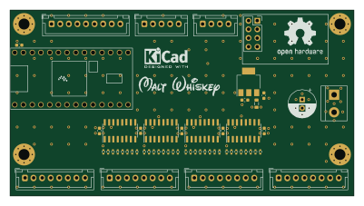 NXP
32Bit shift register
MaltWhiskey
100 × 54 mm56 parts4LNo license763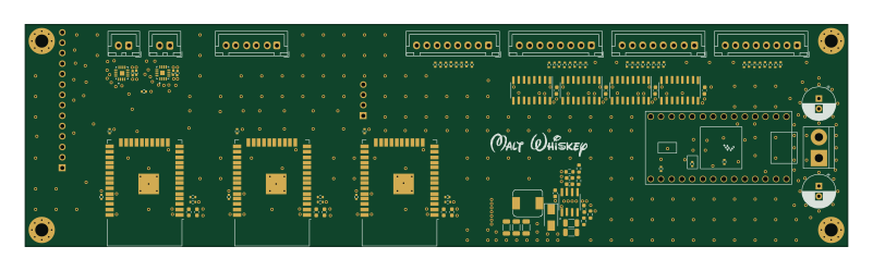 NXP
Mega-Cube-Board
200 × 54 mm100 parts4LNo license763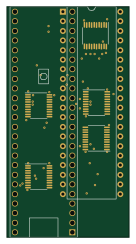 NXP
MCL6809
MicroCoreLabs
32.3 × 61 mm7 parts4LNo license532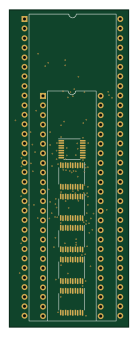 NXP
MCL68
31.6 × 84.1 mm13 parts4LNo license532 NXP
MCL65+
72.6 × 64.1 mm6 parts2LNo license532 NXP
MCLZ8
37.1 × 61.5 mm6 parts4LNo license532