
CAN-Bus-Car-Lights

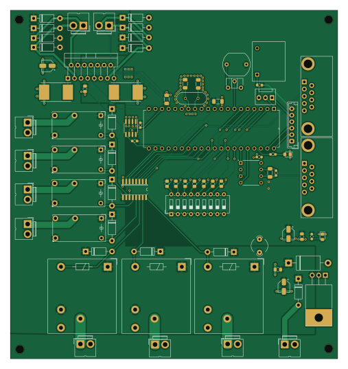
About the CAN-Bus-Car-Lights PCB
CAN-Bus-Car-Lights is an open source PIC PCB design by sergimarsol, published on GitHub under the MIT license. It is a 2-layer board measuring 126.1 × 134.1 mm, with 80 components from 44 distinct parts.
Its main chip is the PIC18F458-I/P, from the PIC family. Other key parts include the LM1117S-5.0, MCP2551-I/P, 24C02C/P, ULN2003 and L298N. By type, the board carries 18 diodes, 15 resistors, 13 connectors, 8 capacitors, 7 relays and 6 ICs.
It belongs with the rf & radio designs in this gallery.
From the project
2-layer KiCad car-lighting board: PIC18F458, CAN transceiver, relay drivers, washer motors, auto-lights
A 2-layer KiCad board that drives a car's exterior lights and headlight-washer motors from a 12 V battery, built around a PIC18F458 with CAN, USART and I²C interfaces.
Group project for Eines de Disseny (Design Tools), part of the Electronic & Telecommunications Engineering degree at the Universitat de Barcelona (spring 2023). The brief was to design the electronics module that controls a car's exterior lighting. The board had to:
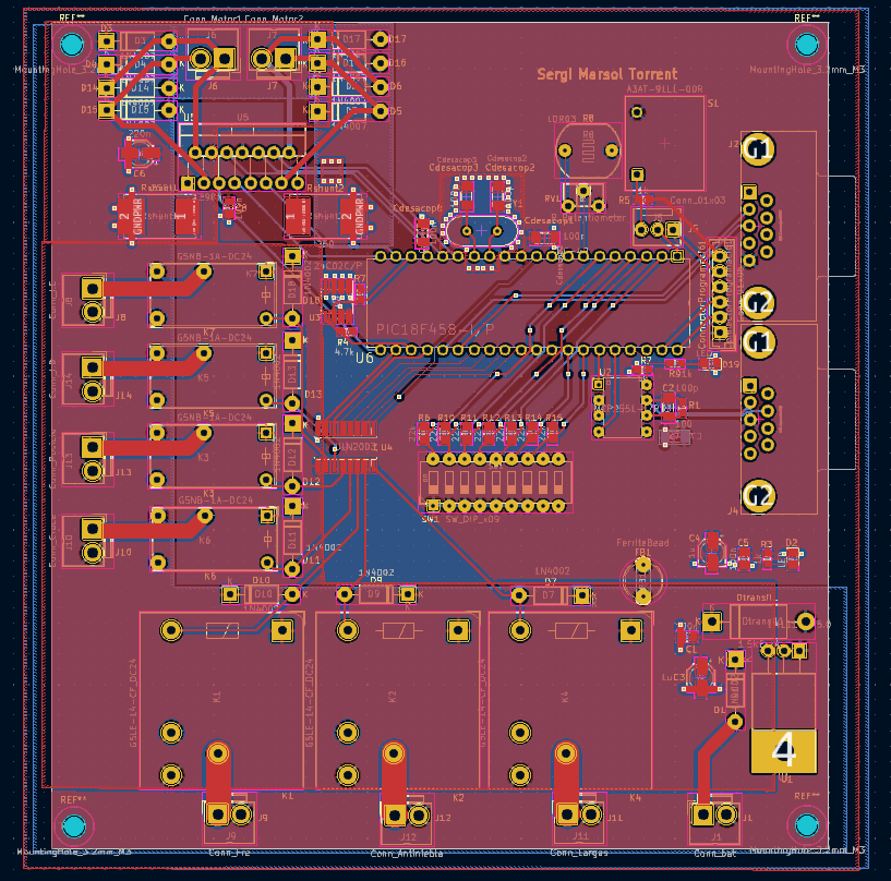
Main components on the CAN-Bus-Car-Lights
CAN-Bus-Car-Lights bill of materials (BOM)
80 components, 44 distinct parts.
| Qty | Part | Footprint | Refs |
|---|---|---|---|
| 1 | LM1117S-5.0 | TO-220-3_Horizontal_TabDown (P2) | U1 |
| 1 | MCP2551-I/P | DIP787W46P254L927H533Q8 | U2 |
| 1 | 24C02C/P | SOIC-8_3.9x4.9mm_P1.27mm | U3 |
| 1 | ULN2003 | SO16 | U4 |
| 1 | L298N | TO-220-15_P2.54x2.54mm_StaggerOdd_Lead4.58mm_Vertical | U5 |
| 1 | PIC18F458-I/P | DIP254P1524X483-40 | U6 |
| 1 | HC-49/U-S8192000ABJB HC-49 | XTAL_HC49P488W43L1150T466H350 | Y1 |
| 1 | Conn_bat | JWT_A3963_1x02_P3.96mm_Vertical | J1 |
| 1 | DB9_ConnectorUSART | DB9 | J2 |
| 1 | DB9_ConnectorCAN | DB9 | J4 |
| 1 | Conn_01x03 | FanPinHeader_1x03_P2.54mm_Vertical | J5 |
| 1 | Conn_Motor1 | JWT_A3963_1x02_P3.96mm_Vertical | J6 |
| 1 | Conn_Motor2 | JWT_A3963_1x02_P3.96mm_Vertical | J7 |
| 1 | Conn_I.E | JWT_A3963_1x02_P3.96mm_Vertical | J8 |
| 1 | Conn_Fre | JWT_A3963_1x02_P3.96mm_Vertical | J9 |
| 1 | Conn_Cruce | JWT_A3963_1x02_P3.96mm_Vertical | J10 |
| 1 | Conn_Largas | JWT_A3963_1x02_P3.96mm_Vertical | J11 |
| 1 | Conn_Antiniebla | JWT_A3963_1x02_P3.96mm_Vertical | J12 |
| 1 | Conn_Posicio | JWT_A3963_1x02_P3.96mm_Vertical | J13 |
| 1 | Conn_I.D | JWT_A3963_1x02_P3.96mm_Vertical | J14 |
Show 24 more
| Qty | Part | Footprint | Refs |
|---|---|---|---|
| 2 | 100n | C_1206_3216Metric_Pad1.33x1.80mm_HandSolder | Cdesacop1, Cdesacop8 |
| 2 | 100p | C_1206_3216Metric_Pad1.33x1.80mm_HandSolder | Cdesacop2, Cdesacop3 |
| 1 | Conn_01x06 | JST_EH_B6B-EH-A_1x06_P2.50mm_Vertical | ConnectorProgramació1 |
| 1 | 1.5KExxA | D_DO-201AE_P15.24mm_Horizontal | Dtransil1 |
| 3 | G5LE-14-CF_DC24 | Relay_SPDT_Finder_40.11 | K1, K2, K4 |
| 4 | G5NB-1A-DC24 | Relay_SPDT_Finder_32.21-x000 | K3, K5, K6, K7 |
| 1 | R_Potentiometer | Potentiometer_ACP_CA6-H2,5_Horizontal | RV1 |
| 2 | 250 | R_Shunt_Vishay_WSR2_WSR3 | Rshunt1, Rshunt2 |
| 1 | A3AT-91L1-00R | SW_A3AT-91L1-00R | S1 |
| 1 | SW_DIP_x09 | SW_DIP_SPSTx09_Slide_6.7x24.42mm_W7.62mm_P2.54mm_LowProfile | SW1 |
| 8 | 1N4002 | D_DO-41_SOD81_P10.16mm_Horizontal | D1, D7, D9, D10, D11, D12, D13, D18 |
| 2 | LED | LED_0805_2012Metric_Pad1.15x1.40mm_HandSolder | D2, D19 |
| 8 | 1N4007 | D_DO-41_SOD81_P10.16mm_Horizontal | D3, D4, D5, D6, D14, D15, D16, D17 |
| 1 | FerriteBead | LairdTech_28C0236-0JW-10 | FB1 |
| 3 | 100n | C_0805_2012Metric_Pad1.18x1.45mm_HandSolder | C1, C5, C8 |
| 1 | 100p | C_1206_3216Metric_Pad1.33x1.80mm_HandSolder | C2 |
| 2 | 1u | CP_Elec_4x5.4 | C3, C4 |
| 1 | 220n | CP_Elec_4x5.4 | C6 |
| 1 | 100n | C_1206_3216Metric_Pad1.33x1.80mm_HandSolder | C7 |
| 1 | 100 | R_0603_1608Metric_Pad0.98x0.95mm_HandSolder | R1 |
| 4 | 1k | R_0603_1608Metric_Pad0.98x0.95mm_HandSolder | R2, R3, R5, R9 |
| 2 | 4.7k | R_0603_1608Metric_Pad0.98x0.95mm_HandSolder | R4, R7 |
| 7 | 22k | R_0805_2012Metric_Pad1.20x1.40mm_HandSolder | R6, R10, R11, R12, R13, R14, R15 |
| 1 | LDR03 | R_LDR_10x8.5mm_P7.6mm_Vertical | R8 |
CAN-Bus-Car-Lights design files
The KiCad project lives in the sergimarsol/CAN-Bus-Car-Lights-PCB repository on GitHub; these links point at the commit this page was built from.
- LayoutCar_lights.kicad_pcb
- SchematicCar_lights.kicad_sch
CAN-Bus-Car-Lights: common questions
What microcontroller does the CAN-Bus-Car-Lights use?
The CAN-Bus-Car-Lights is built around the PIC18F458-I/P, from the PIC family.
How big is the CAN-Bus-Car-Lights PCB?
The CAN-Bus-Car-Lights measures 126.1 × 134.1 mm, has 2 copper layers and is 1.6 mm thick.
How many components are on the CAN-Bus-Car-Lights?
80 components, from 44 distinct parts. The full bill of materials is listed on this page.
Where can I download the CAN-Bus-Car-Lights design files?
From the sergimarsol/CAN-Bus-Car-Lights-PCB repository on GitHub, which has the KiCad layout and the schematic; the links under Design files point to each one.
Can I use the CAN-Bus-Car-Lights design in my own project?
Yes, under the terms of its MIT license, which sergimarsol chose for the repository.
Can I test firmware for the CAN-Bus-Car-Lights without the hardware?
Yes. HardLabs builds a simulation of the board from its netlist and BOM, so you can run and debug PIC firmware against it before you order a PCB.
Similar boards
 PIC
PICPslab hardware
fossasia
99 × 53.3 mm187 parts4LApache-2.01.7k PIC
PICLens
ervanalb
80 × 80 mm53 parts4LNo license515 PIC
PICMicro 8088
skiselev
152.4 × 101.6 mm71 partsGPL-3.0414 PIC
PICGB-LIVE32
Gekkio
51.4 × 61 mm46 parts4LCC-BY-4.0376 PIC
PICGB-MBCTEST
51.4 × 61 mm32 parts2LCC-BY-4.0376 PIC
PICGB-BENCH-G1
100 × 100 mm98 parts4LCC-BY-4.0376