
Antenna analyzer mainboard only

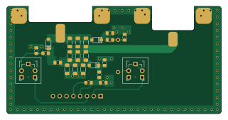
About the Antenna analyzer mainboard only PCB
Antenna analyzer mainboard only is an open source PCB design by shabaz123, published on GitHub. It is a 2-layer board measuring 80 × 40 mm, with 22 components from 13 distinct parts.
By type, the board carries 7 resistors, 6 capacitors, 3 diodes, 2 test points and 1 connector.
It belongs with the rf & radio designs in this gallery.
From the project
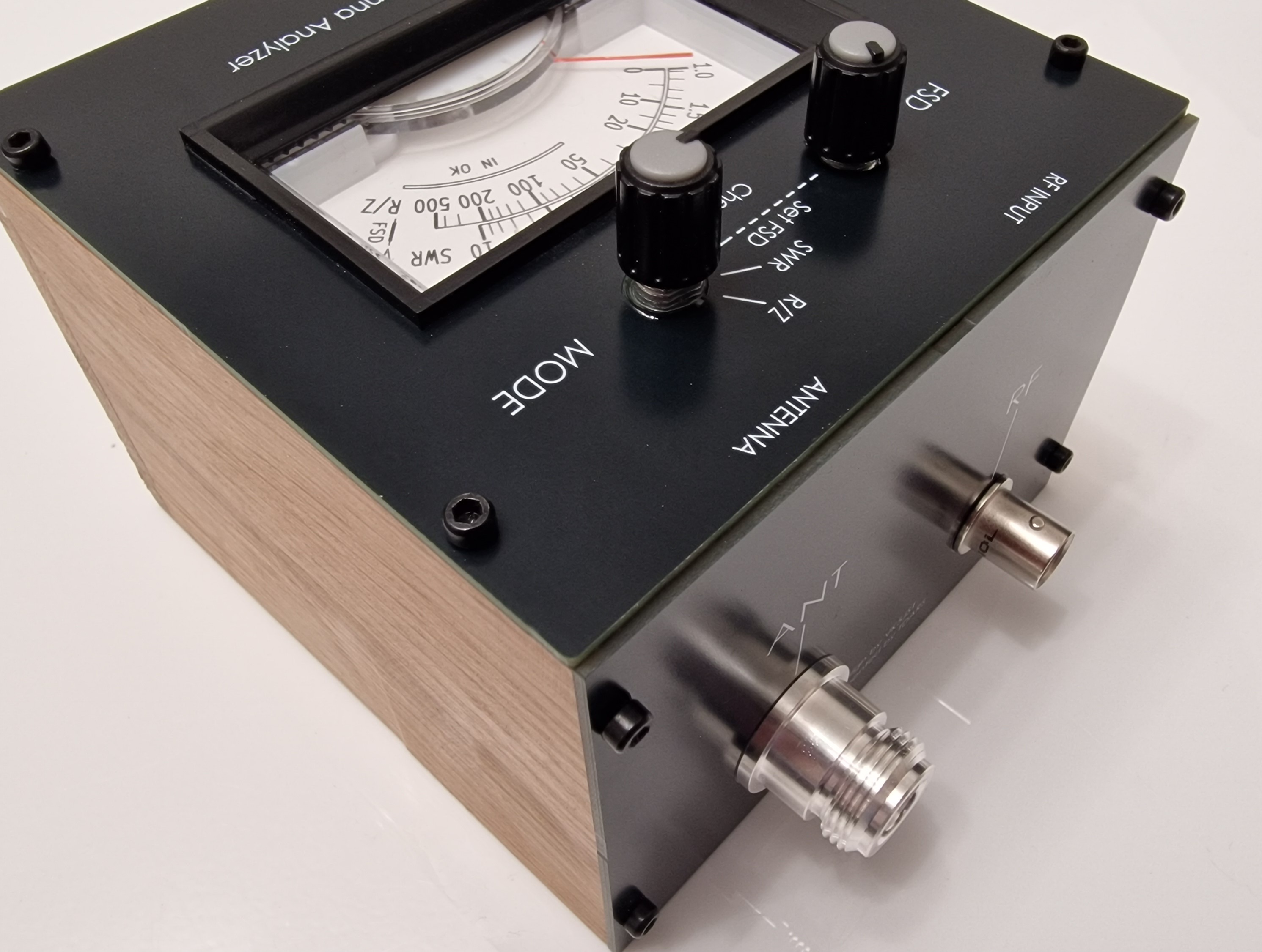
There's a 4-position rotary selector knob. By using that, it is possible to select SWR or R/Z modes, and observe these values on the built-in moving-coil meter movement. The meter is fitted with a detailed scale, although the diagram here just shown LO/HI.
There's a 4-position rotary selector knob. By using that, it is possible to select SWR or R/Z modes, and observe these values on the built-in moving-coil meter movement. The meter is fitted with a detailed scale, although the diagram here just shown LO/HI.
(1) Connect a low-power HF source to the RF input on the instrument, and ensure that nothing is attached to the antenna connector (to simulate a bad antenna)
Antenna analyzer mainboard only bill of materials (BOM)
22 components, 13 distinct parts.
| Qty | Part | Footprint | Refs |
|---|---|---|---|
| 1 | ~ | PinHeader_1x08_P2.54mm_Vertical | J1 |
| 1 | wire-link-shorted | wire-link-12mm | LINK1 |
| 1 | RF INPUT 2W MAX BNC Socket | BNC Socket Edge 031-221-RFX | SK3 |
| 1 | ANTENNA N Socket | N Socket Edge 1-1337417-0 | SK4 |
| 2 | 10k | Potentiometer_Trimmer_Generic_Vertical | TP1, TP2 |
| 3 | 1N5711 | D_SOD-123 | D1, D2, D3 |
| 3 | 470p | C_0805_2012Metric_Pad1.18x1.45mm_HandSolder | C1, C2, C3 |
| 3 | 100n | C_0805_2012Metric_Pad1.18x1.45mm_HandSolder | C4, C5, C6 |
| 3 | 3 x 150R Parallel | 1206-triple-parallel | R1, R2, R3 |
| 1 | 15k | R_0805_2012Metric_Pad1.20x1.40mm_HandSolder | R4 |
| 1 | 10k | R_0805_2012Metric_Pad1.20x1.40mm_HandSolder | R5 |
| 1 | 27k | R_0805_2012Metric_Pad1.20x1.40mm_HandSolder | R6 |
| 1 | 56k | R_0805_2012Metric_Pad1.20x1.40mm_HandSolder | R7 |
Antenna analyzer mainboard only design files
The KiCad project lives in the shabaz123/antenna-analyzer repository on GitHub; these links point at the commit this page was built from.
Antenna analyzer mainboard only: common questions
How big is the Antenna analyzer mainboard only PCB?
The Antenna analyzer mainboard only measures 80 × 40 mm, has 2 copper layers and is 1.6 mm thick.
How many components are on the Antenna analyzer mainboard only?
22 components, from 13 distinct parts. The full bill of materials is listed on this page.
Where can I download the Antenna analyzer mainboard only design files?
From the shabaz123/antenna-analyzer repository on GitHub, which has the KiCad layout and the schematic; the links under Design files point to each one.
Can I use the Antenna analyzer mainboard only design in my own project?
The repository has no license, so all rights stay with shabaz123. Use it as a reference, and ask the author before reusing the design.
More boards in antenna-analyzer
Similar boards
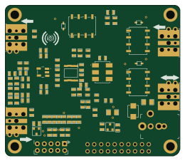
Hat
pa3gsb
65 × 56 mm81 parts2LNo license675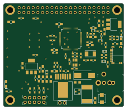
Radioberry juice
65 × 56 mm87 parts2LNo license675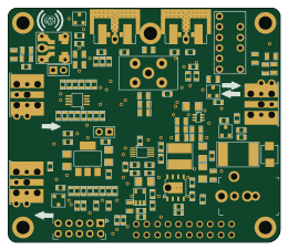
Radioberry preamp
65 × 56 mm137 parts2LNo license675
Goodwatch20
travisgoodspeed
25.6 × 27.6 mm20 parts2LNo license568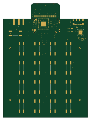
GoodPocketWatch
75.2 × 101.2 mm56 parts2LNo license568
Goodwatch31
25.6 × 27.6 mm23 parts2LNo license568