
4-bit-Adder-Interface-Board

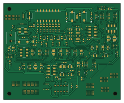
About the 4-bit-Adder-Interface-Board
4-bit-Adder-Interface-Board is an open source PCB design by Shaxzodm2611, published on GitHub. It is a 4-layer board measuring 100 × 82.2 mm, with 125 components from 34 distinct parts.
Other key parts include the LP2985IM5X-4.5/NOPB, SA555DR, CD74HC283M96, LSHD-7503 and SN74LVC1G14DCKR. By type, the board carries 48 ICs, 29 resistors, 25 capacitors, 10 diodes, 4 modules and 3 switches.
From the project
A custom PCB designed to mimic the function of a CPU. Entirely made from discrete logic ICs.
This repository contains KiCad design files for a custom PCB titled 4 Bit - Seven Seg Interface. The project appears to be a discrete-logic interface board built around a 4-bit adder and related support circuitry, intended to drive or interface with a seven-segment display.
The repository description indicates it is:
The project is organized as a KiCad hardware design with schematic sheets and board/layout files, including:
Main components on the 4-bit-Adder-Interface-Board
4-bit-Adder-Interface-Board bill of materials (BOM)
125 components, 34 distinct parts.
| Qty | Part | Footprint | Refs |
|---|---|---|---|
| 1 | LP2985IM5X-4.5/NOPB | DBV0005A_N (16v - 4.5 v VREG)com | U1 |
| 1 | SA555DR | D8 | U2 |
| 1 | CD74HC283M96 | CD74HC283M96 (4-bit Binary Adder) | U3 |
| 1 | LSHD-7503 | DIP10_LSHD-7503_LTO | U4 |
| 4 | SN74LVC1G14DCKR | 1INPUT_NOTGATE | U5, U6, U7, U8 |
| 16 | SN74LVC1G11DBVR | 3-INPUT AND | U9, U10, U16, U17, U18, U19, U27, U28 +8 |
| 15 | SN74LVC1G08DBVR | SOT95P280X145-5N | U11, U12, U13, U20, U22, U23, U24, U25 +7 |
| 3 | CD4072BM96 | 4-INPUT 2-CHN OR | U14, U32, U43 |
| 5 | SN74LVC1G32DCKR | 2-INPUT OR | U15, U21, U33, U34, U47 |
| 1 | NC7SZ332P6X | 3-INPUT OR | U48 |
| 4 | SN74LVC1G175DCKR | DCK0006A_N | A1, A2, A3, A4 |
| 1 | Screw_Terminal_01x02 | Screw-in Terminal | J1 |
| 4 | SN74LVC1G175DCKR | DCK0006A_N | B1, B2, B3, B4 |
| 1 | CFS-0102TB | SW2_CFS-0102TB_NDC | PWR - 9V |
| 1 | 219-8MST | SO16_219-8_CTS | SW2 |
| 2 | CFS-0102TB | SW2_CFS-0102TB_NDC | SW3, SW4 |
| 8 | 150060RS75000 | LED_150060RS75000 | D1, D2, D3, D4, D5, D6, D7, D8 |
| 2 | LED | GLED0805 | D9, D10 |
| 3 | 1uF | C_0603_1608Metric_Pad1.08x0.95mm_HandSolder | C1, C4, C17 |
| 1 | 10uF | 10uF electrolytic Capacitor | C2 |
Show 14 more
| Qty | Part | Footprint | Refs |
|---|---|---|---|
| 3 | 0.01uF | C_0603_1608Metric_Pad1.08x0.95mm_HandSolder | C3, C14, C15 |
| 1 | 2.2uF | C_0603_1608Metric_Pad1.08x0.95mm_HandSolder | C5 |
| 8 | 0.1uF | 0603-0.1uF | C6, C7, C8, C9, C10, C11, C12, C13 |
| 1 | 0.1uF | C_0603_1608Metric_Pad1.08x0.95mm_HandSolder | C16 |
| 1 | 0.1uF | C_0603_1608Metric | C18 |
| 1 | 1uF | C_0603_1608Metric | C19 |
| 3 | 500nF | C_0603_1608Metric_Pad1.08x0.95mm_HandSolder | C20, C21, C25 |
| 3 | 500nF | C_0603_1608Metric | C22, C23, C24 |
| 8 | 330 | R330-0805 | R1, R2, R3, R4, R5, R6, R7, R8 |
| 10 | 10k | R805-10k | R9, R10, R12, R13, R14, R15, R16, R18 +2 |
| 2 | 50 | 0603R-50ohms | R11, R17 |
| 1 | 100k | R_0603_1608Metric | R21 |
| 1 | 6.9k | R_0603_1608Metric | R22 |
| 7 | 124 | R_0603_1608Metric | R23, R24, R25, R26, R27, R28, R29 |
4-bit-Adder-Interface-Board design files
The KiCad project lives in the Shaxzodm2611/4-bit-Adder-Interface-Board repository on GitHub; these links point at the commit this page was built from.
4-bit-Adder-Interface-Board: common questions
How big is the 4-bit-Adder-Interface-Board?
The 4-bit-Adder-Interface-Board measures 100 × 82.2 mm, has 4 copper layers and is 1.6 mm thick.
How many components are on the 4-bit-Adder-Interface-Board?
125 components, from 34 distinct parts. The full bill of materials is listed on this page.
Where can I download the 4-bit-Adder-Interface-Board design files?
From the Shaxzodm2611/4-bit-Adder-Interface-Board repository on GitHub, which has the KiCad layout and the schematic; the links under Design files point to each one.
Can I use the 4-bit-Adder-Interface-Board design in my own project?
The repository has no license, so all rights stay with Shaxzodm2611. Use it as a reference, and ask the author before reusing the design.