
ADS1015 ADC DESKTOP-0LTETPD Oct-18-095654-2021 Conflict


About the ADS1015 ADC DESKTOP-0LTETPD Oct-18-095654-2021 Conflict PCB
ADS1015 ADC DESKTOP-0LTETPD Oct-18-095654-2021 Conflict is an open source PCB design by SolderedElectronics, published on GitHub under the TAPR-OHL-1.0 license. It is a 2-layer board measuring 22 × 22 mm, with 17 components from 13 distinct parts.
Other key parts include the ADS1115. By type, the board carries 5 jumpers, 5 relays, 3 resistors, 1 IC and 1 capacitor.
It belongs with the dev boards & breakouts designs in this gallery.
From the project
Hardware design, BOM, gerbers and 3D files for ADC-12-bit-ADS1015-4-channel-with-PGA-breakout designed by Soldered Electronics.
ADC (Analog Digital Converter) is a device that reads analog signals (just like the analogRead () function in Arduino IDE) and converts them into digital signals that can be read by a microcontroller. This breakout is based on the ADS1015 ADC, which reads values in 12-bit resolution, receives a maximum of 3.3V on its inputs and has a total of 4 channels (which can also be used as two differential). Works great with any microcontroller at 5V. It has 2 easyC connectors for easier connection on I2C communication.

Main components on the ADS1015 ADC DESKTOP-0LTETPD Oct-18-095654-2021 Conflict
ADS1015 ADC DESKTOP-0LTETPD Oct-18-095654-2021 Conflict bill of materials (BOM)
17 components, 13 distinct parts — part numbers from the project's BOM.
| Qty | Part | Footprint | Refs |
|---|---|---|---|
| 1 | ADS1115 | VSSOP | U1 |
| 2 | HOLE_3.2MM HOLE_3.2mm | HOLE_3.2mm | H1, H2 |
| 1 | SMD_JUMPER_3_PAD_TRACE | SMD_JUMPER_3_PAD_TRACE | JP1 |
| 1 | 0X48 0x48 | SMD_JUMPER_CONNECTED | JP2 |
| 1 | 0X49 0x49 | SMD_JUMPER | JP3 |
| 1 | 0X4A 0x4A | SMD_JUMPER | JP4 |
| 1 | 0X4B 0x4B | SMD_JUMPER | JP5 |
| 1 | HEADER_MALE_5X1 | HEADER_MALE_5X1 | K1 |
| 1 | HEADER_MALE_4X1 | HEADER_MALE_4X1 | K2 |
| 2 | easyC-SMD | easyC-connector | K3, K4 |
| 1 | HEADER_MALE_1X1 | HEADER_MALE_1X1 | K5 |
| 1 | 0.1UF 0.1uF | 0603C | C1 |
| 3 | 10K 10k | 0603R | R1, R2, R3 |
ADS1015 ADC DESKTOP-0LTETPD Oct-18-095654-2021 Conflict design files
The KiCad project lives in the SolderedElectronics/ADC-12-bit-ADS1015-4-channel-with-PGA-breakout-hardware-design repository on GitHub; these links point at the commit this page was built from.
ADS1015 ADC DESKTOP-0LTETPD Oct-18-095654-2021 Conflict: common questions
How big is the ADS1015 ADC DESKTOP-0LTETPD Oct-18-095654-2021 Conflict PCB?
The ADS1015 ADC DESKTOP-0LTETPD Oct-18-095654-2021 Conflict measures 22 × 22 mm, has 2 copper layers and is 1.6 mm thick.
How many components are on the ADS1015 ADC DESKTOP-0LTETPD Oct-18-095654-2021 Conflict?
17 components, from 13 distinct parts, with part numbers taken from the project's own BOM. The full bill of materials is listed on this page.
Where can I download the ADS1015 ADC DESKTOP-0LTETPD Oct-18-095654-2021 Conflict design files?
From the SolderedElectronics/ADC-12-bit-ADS1015-4-channel-with-PGA-breakout-hardware-design repository on GitHub, which has the KiCad layout and the BOM; the links under Design files point to each one.
Can I use the ADS1015 ADC DESKTOP-0LTETPD Oct-18-095654-2021 Conflict design in my own project?
Yes, under the terms of its TAPR-OHL-1.0 license, which SolderedElectronics chose for the repository.
More boards in ADC-12-bit-ADS1015-4-channel-with-PGA-breakout-hardware-design

Similar boards
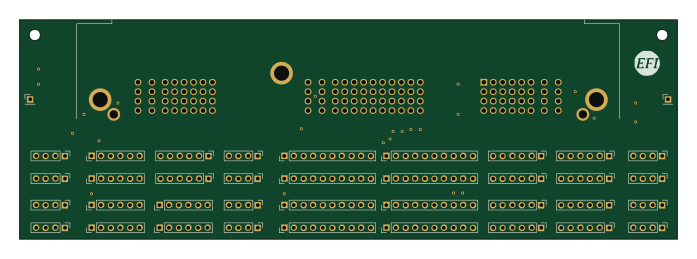
Breakout 112pin Connector
rusefi
174 × 58 mm39 parts2LGPL-3.01.2k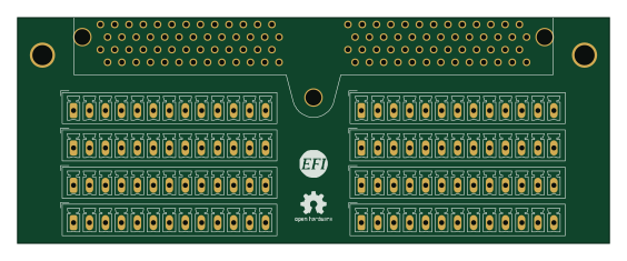
Eecv breakout
140.8 × 53.7 mm9 parts4LGPL-3.01.2k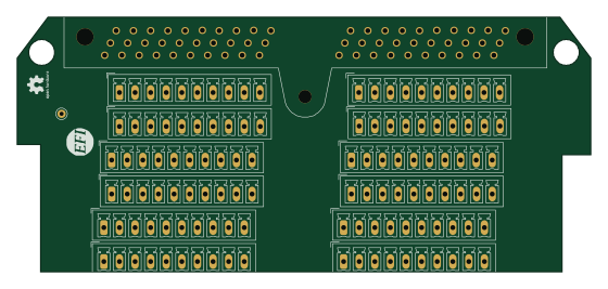
Breakout 60pin EEC-IV
139.7 × 62.2 mm15 parts2LGPL-3.01.2k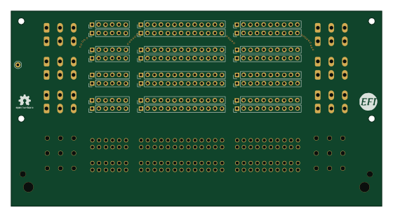
134pin 7-967288-1
139.7 × 73.7 mm38 parts2LGPL-3.01.2k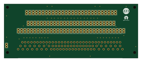
88 Pin Vag Breakout
142 × 58 mm91 parts2LGPL-3.01.2k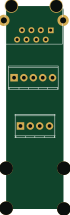
Rj45 breakout
rene-dev
15.2 × 53.8 mm3 parts2LGPL-3.0979