
2G GSM breakout

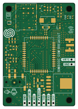
About the 2G GSM breakout
2G GSM breakout is an open source PCB design by SolderedElectronics, published on GitHub under the TAPR-OHL-1.0 license. It is a 2-layer board measuring 38 × 54 mm, with 51 components from 30 distinct parts.
Other key parts include the LP38512-ADJ, SIM800C and SMF05CT1G. By type, the board carries 17 resistors, 14 capacitors, 5 relays, 4 transistors, 3 ICs and 3 diodes.
It belongs with the dev boards & breakouts designs in this gallery.
From the project
Hardware design, BOM, gerbers and 3D files for GSM-communications-SIM800-breakout designed by Soldered Electronics.
This repository contains all design files for , organized as follows:
- CAD folder: Contains KiCAD design files, including: - Schematics - PCB layout - Panel PCB layout - Source 3D files in Fusion360, if any - All files are sorted by version with a detailed change log. - OUTPUTS folder: Includes all production-ready files, such as: - Bill of Materials (BOM) and interactive BOM (iBOM) - PDF versions of schematics - 3D .step file of the board - 3D-printable models - Gerber files for PCB manufacturing - Image of the pinout of the board - Product image - Compliance, legal and generic sales…

Main components on the 2G GSM breakout
2G GSM breakout bill of materials (BOM)
51 components, 30 distinct parts — part numbers from the project's BOM.
| Qty | Part | Footprint | Refs |
|---|---|---|---|
| 1 | LP38512-ADJ | TO-263-5 | U1 |
| 1 | SIM800C | SIM800C | U2 |
| 1 | SMF05CT1G | SOT-363 | U3 |
| 4 | NPN-SOT-23-3 | SOT-23-3 | Q1, Q2, Q3, Q4 |
| 4 | HOLE_3.2MM HOLE_3.2mm | HOLE_3.2mm | H1, H2, H3, H4 |
| 1 | SMD-JUMPER-CONNECTED_TRACE_SLODERMASK | SMD-JUMPER-CONNECTED_TRACE_SLODERMASK | JP1 |
| 1 | 3.5MM_JACK 3.5mm_jack | 3.5mm_jack | K1 |
| 1 | HEADER_MALE_2X1 | HEADER_MALE_2X1 | K2 |
| 1 | HEADER_MALE_7X1 | HEADER_MALE_7X1 | K3 |
| 1 | SF72S006VBAR2500 | SF72S006VBAR2500 | K4 |
| 1 | Antenna Connector | Antenna Connector | K5 |
| 1 | purple | 0402LED | D1 |
| 1 | green | 0402LED | D2 |
| 1 | MBR0530T1G | SOD−123 | D3 |
| 3 | 10UF 10uF | 1206C | C1, C2, C8 |
| 2 | 10PF 10pF | 0603C | C3, C4 |
| 2 | 33PF 33pF | 0603C | C5, C6 |
| 1 | 2.2NF 2.2nF | 0603C | C7 |
| 1 | 100UF 100uF | T491X107K025AT | C9 |
| 1 | 1UF 1uF | 0402C | C10 |
Show 10 more
| Qty | Part | Footprint | Refs |
|---|---|---|---|
| 1 | 33PF 33pF | 0402C | C11 |
| 1 | 10PF 10pF | 0402C | C12 |
| 1 | 22PF 22pF | 0402C | C13 |
| 1 | 100NF 100nF | 0402C | C14 |
| 1 | 2K2 2k2 | 0402R | R1 |
| 6 | 4K7 4k7 | 0603R | R2, R3, R10, R14, R15, R16 |
| 4 | 47K 47k | 0603R | R4, R6, R9, R17 |
| 2 | 2K2 2k2 | 0603R | R5, R7 |
| 1 | 300R | 0603R | R8 |
| 3 | 51R | 0603R | R11, R12, R13 |
2G GSM breakout design files
The KiCad project lives in the SolderedElectronics/GSM-communications-SIM800-breakout-hardware-design repository on GitHub; these links point at the commit this page was built from.
2G GSM breakout: common questions
How big is the 2G GSM breakout?
The 2G GSM breakout measures 38 × 54 mm, has 2 copper layers and is 1.6 mm thick.
How many components are on the 2G GSM breakout?
51 components, from 30 distinct parts, with part numbers taken from the project's own BOM. The full bill of materials is listed on this page.
Where can I download the 2G GSM breakout design files?
From the SolderedElectronics/GSM-communications-SIM800-breakout-hardware-design repository on GitHub, which has the KiCad layout, the schematic and the BOM; the links under Design files point to each one.
Can I use the 2G GSM breakout design in my own project?
Yes, under the terms of its TAPR-OHL-1.0 license, which SolderedElectronics chose for the repository.
More boards in GSM-communications-SIM800-breakout-hardware-design
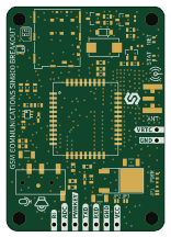
Similar boards
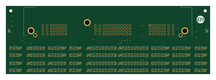
Breakout 112pin Connector
rusefi
174 × 58 mm39 parts2LGPL-3.01.2k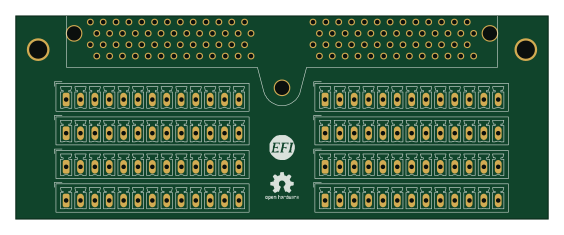
Eecv breakout
140.8 × 53.7 mm9 parts4LGPL-3.01.2k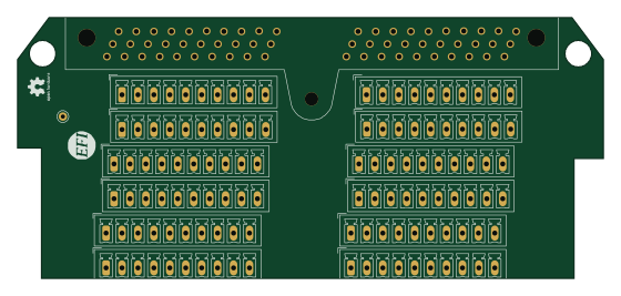
Breakout 60pin EEC-IV
139.7 × 62.2 mm15 parts2LGPL-3.01.2k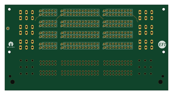
134pin 7-967288-1
139.7 × 73.7 mm38 parts2LGPL-3.01.2k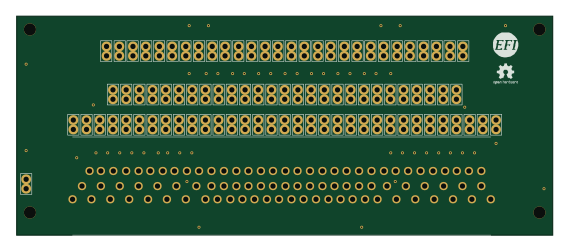
88 Pin Vag Breakout
142 × 58 mm91 parts2LGPL-3.01.2k
Rj45 breakout
rene-dev
15.2 × 53.8 mm3 parts2LGPL-3.0979