
USB-UART-CH340C-converter board hardware design

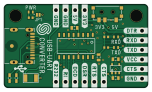
About the USB-UART-CH340C-converter board hardware design
USB-UART-CH340C-converter board hardware design is an open source PCB design by SolderedElectronics, published on GitHub under the TAPR-OHL-1.0 license. It is a 2-layer board measuring 38 × 22 mm, with 23 components from 18 distinct parts.
Other key parts include the CH340C and SE5218. By type, the board carries 5 resistors, 4 relays, 4 capacitors, 3 diodes, 2 ICs and 1 fuse.
It belongs with the usb & debug tools designs in this gallery.
From the project
Hardware design, BOM, gerbers and 3D files for USB-UART-CH340C-converter-board designed by Soldered Electronics.
This small USBUART adapter converts USB communication into UART (serial) communication, and everything you might need is already on this small board. In addition to the classic UART pins that are arranged in the standard layout: DTR, RXD, TXD, VCC, CTS, GND, other pins available of the CH340 chip are also available on header: RS232, RI, DCD, DSR, RST and CTS. Indication LEDs show activity on RXT and TXD lines, and a 500mA fuse protects this programmer, the USB port of the computer that is connected, and other devices connected to it from damage.

Main components on the USB-UART-CH340C-converter board hardware design
USB-UART-CH340C-converter board hardware design bill of materials (BOM)
23 components, 18 distinct parts — part numbers from the project's BOM.
| Qty | Part | Footprint | Refs |
|---|---|---|---|
| 1 | CH340C | SOP-16 | U1 |
| 1 | SE5218 | SOT-23-5 | U2 |
| 1 | 1206FUSE-500mA | 1206FUSE | F1 |
| 2 | HOLE_3.2mm | HOLE_3.2mm | H1, H2 |
| 1 | SMD-JUMPER-CONNECTED_TRACE_SLODERMASK | SMD-JUMPER-CONNECTED_TRACE_SLODERMASK | JP1 |
| 1 | U262-161N-4BVC11 | U262-161N-4BVC11 | K1 |
| 1 | HEADER_MALE_6X1 | HEADER_MALE_6X1 | K2 |
| 1 | FTDI_HEADER | HEADER_MALE_6X1 | K3 |
| 1 | HEADER_MALE_4X1 | HEADER_MALE_4X1 | K4 |
| 1 | SS-3292S-L1 | SS-3292S-L1 | S1 |
| 1 | white | 0402LED | D1 |
| 1 | blue | 0402LED | D2 |
| 1 | purple | 0402LED | D3 |
| 2 | 0.1uF | 0603C | C1, C2 |
| 2 | 2.2uF | 0603C | C3, C4 |
| 2 | 5.1k | 0603R | R1, R2 |
| 2 | 10k | 0402R | R3, R4 |
| 1 | 2k2 | 0402R | R5 |
USB-UART-CH340C-converter board hardware design design files
The KiCad project lives in the SolderedElectronics/USB-UART-CH340C-converter-board-hardware-design repository on GitHub; these links point at the commit this page was built from.
USB-UART-CH340C-converter board hardware design: common questions
How big is the USB-UART-CH340C-converter board hardware design?
The USB-UART-CH340C-converter board hardware design measures 38 × 22 mm, has 2 copper layers and is 1.6 mm thick.
How many components are on the USB-UART-CH340C-converter board hardware design?
23 components, from 18 distinct parts, with part numbers taken from the project's own BOM. The full bill of materials is listed on this page.
Where can I download the USB-UART-CH340C-converter board hardware design design files?
From the SolderedElectronics/USB-UART-CH340C-converter-board-hardware-design repository on GitHub, which has the KiCad layout, the schematic and the BOM; the links under Design files point to each one.
Can I use the USB-UART-CH340C-converter board hardware design design in my own project?
Yes, under the terms of its TAPR-OHL-1.0 license, which SolderedElectronics chose for the repository.
Similar boards
FW-EC-DongleHiderPlus
LeoDJ
28.2 × 26.1 mm14 parts4LCERN-OHL-W-2.0490
Relatively-Universal-ROM-Programmer
AndersBNielsen
68.8 × 53.6 mm141 parts2LGPL-3.0253
Ovc5
osrf
98 × 97 mm197 parts6LApache-2.0208
Easy pdk programmer hardware
free-pdk
26.7 × 21.6 mm28 parts2LCC-BY-SA-4.0206
27c160-tl866-adapter
mafe72
82.4 × 43.1 mm10 partsGPL-3.0147
STM32 VGM Player YM2612 SN76489
AidanHockey5
138.4 × 91.4 mm84 parts2LAGPL-3.0117