
STS1 GS TRX Switch

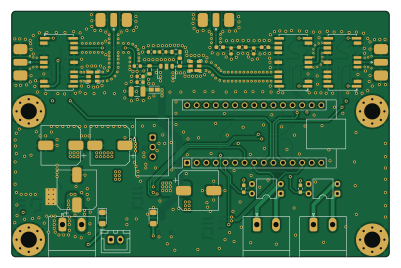
About the STS1 GS TRX Switch PCB
STS1 GS TRX Switch is an open source AVR/Arduino PCB design by SpaceTeam, published on GitHub under the MIT license. It is a 4-layer board measuring 100 × 65 mm, with 103 components from 49 distinct parts.
Its main chip is the Arduino_Nano_v2.x, from the AVR/Arduino family. Other key parts include the PC817, PGA-103+, BTT6050-2EKA, TSR2-2450 and TPS54360DDA. By type, the board carries 33 capacitors, 25 resistors, 11 diodes, 10 inductors, 8 connectors and 7 ICs.
It belongs with the rf & radio designs in this gallery.
From the project
Simple PCB for transmit/receive switching for our groundstation
This boards provides sequencing and switching for transmit and receive path of a satellite groundstation based on two galvanically isolated inputs. It features an on-board LNA with filter and pre and post filtering for an external power amplifier. It also provides ~30V switched for the PA derived from one common 48V supply.
It is controlled by an Arduino Nano which is used for timing. It features two high-side MOSFET outputs for enabling a PA and LNA and three coaxial relays for RX/TX switching and antenna grounding (when neither RX nor TX is enabled).
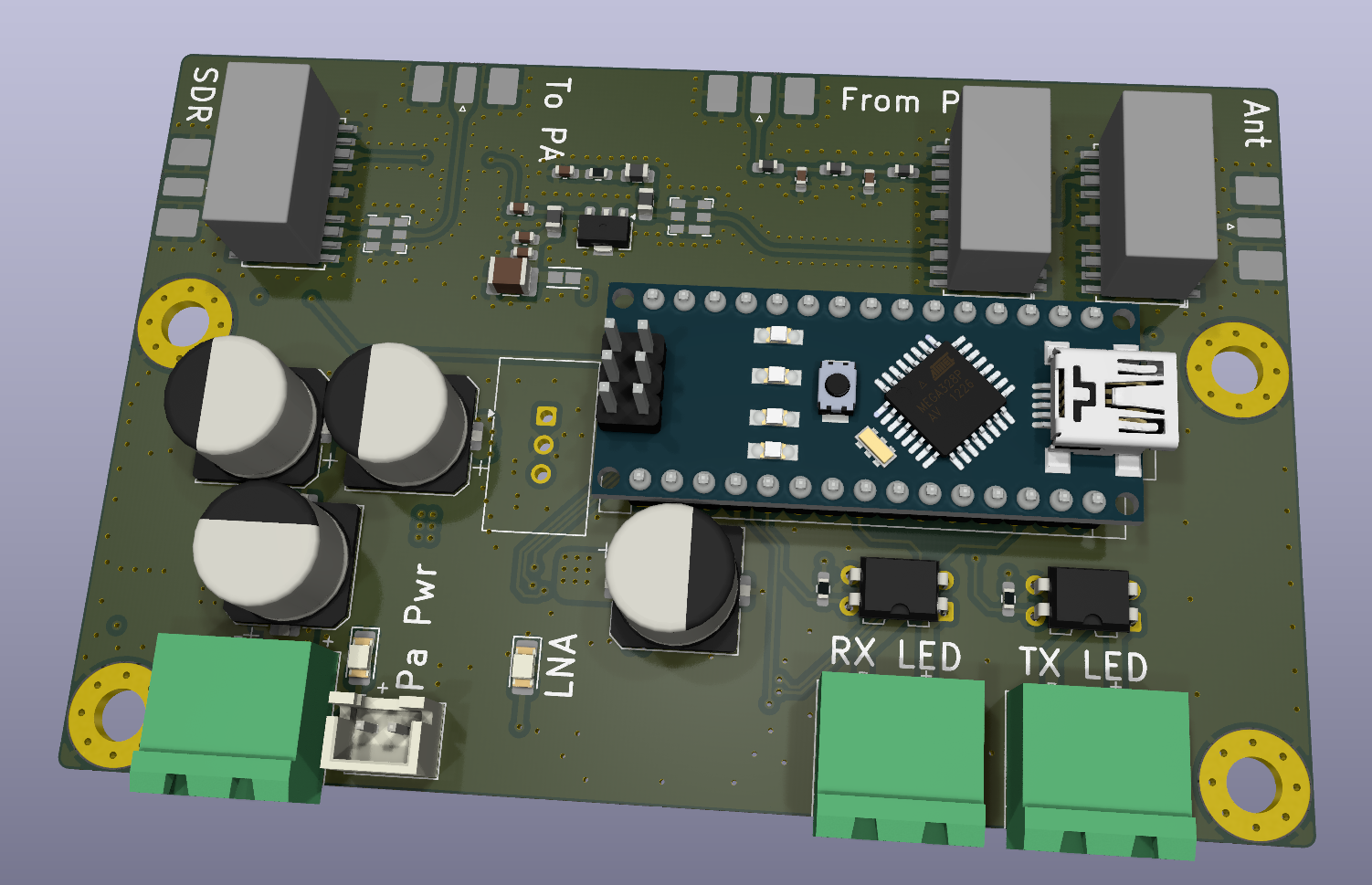
Main components on the STS1 GS TRX Switch
STS1 GS TRX Switch bill of materials (BOM)
103 components, 49 distinct parts.
| Qty | Part | Footprint | Refs |
|---|---|---|---|
| 2 | PC817 | DIP-4_W7.62mm | U1, U2 |
| 1 | PGA-103+ | SOT-89-3 | U3 |
| 2 | BTT6050-2EKA | Infineon_PG-DSO-14-40-EP_3.9x8.65mm_P1.27mm | U4, U6 |
| 1 | TSR2-2450 | Converter_DCDC_TRACO_TSR2-xxxx_THT | U5 |
| 1 | TPS54360DDA | TI_SO-PowerPAD-8_ThermalVias | U7 |
| 1 | Arduino_Nano_v2.x | Arduino_Nano | A1 |
| 3 | BC847 | SOT-23 | Q1, Q2, Q3 |
| 2 | SF2446E | Filter_SAW-6_3.0x3.0mm | X1, X2 |
| 1 | SDR | SMA_Molex_73251-2120_EdgeMount_Horizontal | J1 |
| 1 | PA_Pwr | JST_XH_B2B-XH-A_1x02_P2.50mm_Vertical | J2 |
| 1 | To_PA | SMA_Molex_73251-2120_EdgeMount_Horizontal | J3 |
| 1 | From_PA | SMA_Molex_73251-2120_EdgeMount_Horizontal | J5 |
| 1 | Antenna | SMA_Molex_73251-2120_EdgeMount_Horizontal | J6 |
| 1 | RX_LED | PhoenixContact_MSTBA_2,5_2-G-5,08_1x02_P5.08mm_Horizontal | J7 |
| 1 | TX_LED | PhoenixContact_MSTBA_2,5_2-G-5,08_1x02_P5.08mm_Horizontal | J8 |
| 1 | 48V_Supply | PhoenixContact_MSTBA_2,5_2-G-5,08_1x02_P5.08mm_Horizontal | J9 |
| 3 | HF3-53 | Relay_SPDT_AXICOM_HF3Series_50ohms_Pitch1.27mm | K1, K2, K3 |
| 5 | BAS16W | SOT-323_SC-70 | D1, D2, D3, D4, D5 |
| 1 | TRX_Sw_1 | LED_1206_3216Metric_Pad1.42x1.75mm_HandSolder | D6 |
| 1 | TRX_Sw_2 | LED_1206_3216Metric_Pad1.42x1.75mm_HandSolder | D7 |
Show 29 more
| Qty | Part | Footprint | Refs |
|---|---|---|---|
| 1 | Ant_GND_Sw | LED_1206_3216Metric_Pad1.42x1.75mm_HandSolder | D8 |
| 1 | PA_Sw | LED_1206_3216Metric_Pad1.42x1.75mm_HandSolder | D9 |
| 1 | LNA_Sw | LED_1206_3216Metric_Pad1.42x1.75mm_HandSolder | D11 |
| 1 | CDBC560-G | D_SMC_Handsoldering | D12 |
| 1 | 600R/0.5A | Murata-BLM18-0.15-t0.8-0-0-IPC_A | FB1 |
| 2 | LQW18AN33NJ80D 33nH | L_0603_1608Metric_Pad1.05x0.95mm_HandSolder | L1, L6 |
| 1 | LQW18AN51NG80D 51nH | L_0603_1608Metric_Pad1.05x0.95mm_HandSolder | L2 |
| 2 | LQW2BASR22J00L 220nH | L_0805_2012Metric | L3, L5 |
| 1 | LQW2BASR39J00L 390nH | L_0805_2012Metric | L4 |
| 2 | ASPI-4030S-5R6M-T 5.6µH | L_Abracon_ASPI-4030S | L7, L8 |
| 1 | SRR1210-270M 27µH | L_Bourns_SRR1210A | L9 |
| 4 | 10µ | C_1210_3225Metric_Pad1.33x2.70mm_HandSolder | C1, C24, C25, C36 |
| 9 | 1µ | C_0603_1608Metric_Pad1.08x0.95mm_HandSolder | C4, C5, C6, C7, C8, C9, C19, C20 +1 |
| 1 | 330pF | C_0603_1608Metric | C10 |
| 4 | 100pF | C_0603_1608Metric | C11, C14, C17, C18 |
| 1 | 100nF | C_0603_1608Metric | C12 |
| 2 | 7.5pF | C_0603_1608Metric | C15, C16 |
| 4 | 100µ | CP_Elec_10x10 | C22, C29, C30, C35 |
| 5 | 10µ | C_0805_2012Metric_Pad1.18x1.45mm_HandSolder | C23, C26, C27, C28, C31 |
| 1 | 100n | C_0805_2012Metric_Pad1.18x1.45mm_HandSolder | C32 |
| 1 | 100p | C_0603_1608Metric_Pad1.08x0.95mm_HandSolder | C33 |
| 1 | 7.5n | C_1206_3216Metric_Pad1.33x1.80mm_HandSolder | C34 |
| 15 | 10k | R_0603_1608Metric_Pad0.98x0.95mm_HandSolder | R1, R2, R3, R4, R5, R6, R8, R9 +7 |
| 3 | 1k | R_0603_1608Metric_Pad0.98x0.95mm_HandSolder | R10, R11, R12 |
| 1 | 120 | R_0603_1608Metric | R14 |
| 2 | 1.8k | R_0603_1608Metric_Pad0.98x0.95mm_HandSolder | R18, R20 |
| 2 | 221k | R_0603_1608Metric_Pad0.98x0.95mm_HandSolder | R23, R24 |
| 1 | 370k | R_0603_1608Metric_Pad0.98x0.95mm_HandSolder | R25 |
| 1 | 11k | R_0603_1608Metric_Pad0.98x0.95mm_HandSolder | R26 |
STS1 GS TRX Switch design files
The KiCad project lives in the SpaceTeam/STS1_GS_TRX_Switch repository on GitHub; these links point at the commit this page was built from.
- LayoutSTS1_GS_TRX_Switch.kicad_pcb
- SchematicSTS1_GS_TRX_Switch.kicad_sch
STS1 GS TRX Switch: common questions
What microcontroller does the STS1 GS TRX Switch use?
The STS1 GS TRX Switch is built around the Arduino_Nano_v2.x, from the AVR/Arduino family.
How big is the STS1 GS TRX Switch PCB?
The STS1 GS TRX Switch measures 100 × 65 mm, has 4 copper layers and is 1.6062 mm thick.
How many components are on the STS1 GS TRX Switch?
103 components, from 49 distinct parts. The full bill of materials is listed on this page.
Where can I download the STS1 GS TRX Switch design files?
From the SpaceTeam/STS1_GS_TRX_Switch repository on GitHub, which has the KiCad layout and the schematic; the links under Design files point to each one.
Can I use the STS1 GS TRX Switch design in my own project?
Yes, under the terms of its MIT license, which SpaceTeam chose for the repository.
Can I test firmware for the STS1 GS TRX Switch without the hardware?
Yes. HardLabs builds a simulation of the board from its netlist and BOM, so you can run and debug AVR/Arduino firmware against it before you order a PCB.
Similar boards
 AVR/Arduino
Magspoof
samyk
35 × 29 mm11 parts2LNo license4.2k AVR/Arduino
Redox keyboard
mattdibi
162.2 × 126.5 mm77 parts2LMIT2.0k AVR/Arduino
Labrador
espotek-org
36.8 × 34.7 mm75 parts2LNo license1.2k AVR/Arduino
ModuleV450
stuartpittaway
30 × 61.4 mm39 parts2LCC-BY-NC-4.01.1k AVR/Arduino
V4
30 × 50 mm38 parts2LCC-BY-NC-4.01.1k AVR/Arduino
Discipline
coseyfannitutti
304.9 × 122.8 mm170 parts2LCC-BY-NC-4.01.0k